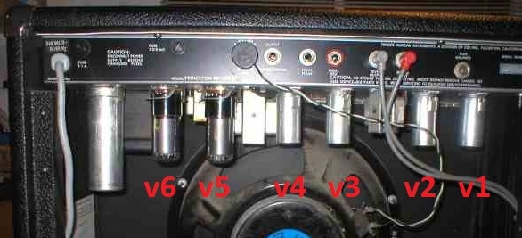
looking in the back of the amp, left to right: 6V6GTA, 6V6GTA,12AX7, 12AX7, 12AT7, 12AX7
looking in the back of the amp, left to right: 6V6GTA, 6V6GTA,12AX7, 12AX7, 12AT7, 12AX7
That said, one of the
satisfying things about all-valve amps is their comparative
simplicity. Only 5 or 6 stages of amplification and the tiny
guitar signal is beefed up to potential pain level; and each of
those stages is fairly easy to change. In modern solid-state amps,
so many chips are used, each one containing hundreds of
transistors, the simplicity is lost, the sound must suffer, and
experimentation is very difficult.
You can read up a little on
who makes valves these days. Despite there being many brand names
out there, if it's a current-production valve, it came from one of
only four factories; one in China, two in Russia, and one in
Slovakia. It's embarrassing to get excited about the "differences"
between 2 brands and then discover the only difference is in the
label. You can pay more for more testing, and that may be a good
thing, but don't forget, this only eliminates the ones you didn't
buy - it doesn't improve the tone of the ones on sale.
I should probably add that,
the more I discuss and read up on this, the more I get the
impression that the speaker's more important. If your present
valves are working OK, and not old and tired, then changing
the speaker will have a far bigger impact on your
tone. (Unless you know different; email me...)
Myths about Valves
(1) You must use
7025s, not 12AX7
No... the 7025 was devised as
a low-noise, less-microphonic 12AX7, with coiled heaters to reduce
hum. In reality ECC83 or 12AX7 are way more readily available,
cheaper, and will work just as well in the three places where 7025
is specified. If you go to some valve / tube -selling websites and
search for 7025, they take you to 12AX7s! My PRII is low-noise
with every 12AX7 I've tried and I don't feel like paying the extra
for 7025s! September 2024 - EH are doing a 7025 costing not much
more than their 12AX7, so if you're really picky, go for it...
(2) Don't touch the glass
You shouldn't touch them when
they're hot because you'll be hurt! Duh! But these aren't halogen
light bulbs, and the sweat from your fingers won't harm the valve.
But don't shock them mechanically while they're hot. Frequent
handling can rub the ink off, which might reduce the secondhand
value of a famous-name valve. And try to hold power valves by the
plastic base when fitting/removing from the amp, so reducing the
risk of detaching the base from the glass.
(3) If you use low-gain preamp valves, the power valves
have to work harder, which is a good thing
No. If you use low-gain preamp
valves, you may or may not get a different tone, which you may or
may not like. Then, to get the same audio volume as before, you'll
have to turn the master volume knob up to a higher number on the
dial. But if it's the same audio volume as before, then the power
valves are doing exactly the same amount of work as before. If you
want the power stage to work harder without an increase in audio
volume, you'll have to use a less sensitive speaker or throw away
some of the final output with a power attenuator. BUT if you're
looking for tube distortion, a high-gain valve in the first
position will probably create clipping early in the signal chain;
not always a good idea. A low-gain valve in the first position
keeps it clean further into the amp, leaving you with the option
of turning up the master volume to overdrive only the power stage.
If you're looking for that classic tube distortion you're more
likely to get it that way.
----------------------
What the valves (tubes) doV1 on Schematic - Input
valve (7025, ECC83 = 12AX7 work fine)
This one is close to the serial number plate. It's used as two
separate stages of amplification in one glass bottle. One stage
provides the first amplification after your weak little guitar
signal arrives, almost exhausted, at the input jack. NB the amp's
volume control comes after the first 'half' of this valve,
not before, so it's not just a duplicate of your guitar's volume
knob. Then comes the bass, mid, and treble controls, and the
volume knob; the other 'half' of this valve then provides another
stage of amplification. How the
tone stack works
You can get different tones,
and more or less noise, simply by playing with different
combinations of 'volume' and 'master'.
Note that , when there's no
jack plug in the front panel socket, the inputs of both halves of
V1 are grounded by a switch in the jack socket. This cuts down on
noise.
Obviously you want all
the valves working well, but the signal passes through this valve
twice, while it's still at a low level; so if this one's a
bit noisy and tired, the others won't be able to help no matter
how great they are. If you're minus a valve cover, don't let this
valve go without, as in theory it's the most sensitive to
interference.
Oct 2010 - I'm now using a
12AY7 in this position. On an arbitrary scale, 12AX7s are rated
'100' for gain - 12AY7 are rated '40'. This cuts down the gain and
ultimately the maximum volume you can get out of the amp, but (on
my amp at least) it makes the clean sound just a little cleaner.
This is not the same as simply turning down the front-end volume
control, though I can't explain why! Using a lower gain valve here
also cleans up the reverb a little. Anyway, 12AY7s are in current
production by (or at least branded as) Electro-Harmonix, Ruby, JJ,
TAD, andGroove Tubes.
V2 - Reverb Driver and
'lead' distortion (12AT7)
This valve is also a dual
triode but the 2 little amplifiers are wired in parallel to create
one preamp with enough current-capability to function properly. It
has 2 jobs.
(1) It amplifies the signal considerably in order to wiggle
the springs in the reverb unit. And it's doing it all the time,
even when you haven't selected reverb - the 'reverb' knob comes
after V3a (below). BUT
(2) irrespective of reverb setting, when you select the
'lead' effect, most of the (massive) signal from V2 is mixed into
the sound via V3b, resulting in V3b being distorted (= "preamp
distortion) and offering you a kind of valve overdrive sound.
Therefore the reverb depth
drops to near-zero when 'lead' is also selected. This is a
universal problem on the PRII and I know of no cure. Even if the
reverb level could be kept up (maybe with some component value
changes?), it would be a reverb of the clean sound only. Ideally
the reverb would come after the distortion stage, so you could
simulate "an overdriven amp in a big room", but without a redesign
this amp will not do that. Buy a reverb pedal.
When in 'clean' mode
(non-lead), the PRII has a reputation for useful reverb only from
knob position 1-3; turn it up higher and all you get is more mush.
If your PRII has the reverb tank mounted vertically,
screwed to the side wall of the cabinet, put it in the base of
the cab instead. The tank was designed to be horizontal and the
reverb quality will improve by this
simple operation. But I found by accident that
different 12AT7s can affect this, sometimes improving it.
Lower-gain valves gives more useful adjustment; I use at 12AU7 in
this position for this reason. That reduces the 'lead' sound to a
kind of fat boost instead of distortion. The amp will work without
this valve - but minus reverb and lead (overdrive). I used to say
on this web page that you needn't bother putting an expensive
valve here. But I was wrong. In Feb 06; I put an old Mazda 12AT7
in here (with an old Mazda 12AX7 in V3) and the lead sound is much
better. Then I put a used Brimar 12AT7 in V2 and the "lead" sound
is now very usable. So don't let anyone tell you the "lead" effect
is useless; you just have to be lucky with your valves. I buy used
valves from eBay, sometimes without even a guarantee that they
work. They don't cost much for Mazdas, Brimars and Mullards, and
they nearly always work.
V3 - Reverb Pickup and
final preamp (7025, ECC83 = 12AX7 work fine)
(Nearest 'pedal red' socket.) Like V1, this works in two
'halves'. The first 'half' picks up the signal from the reverb
unit and passes it on via the reverb knob. The other 'half'
provides another stage of gain for the main signal path through
the amp. This second 'half' is the bit which is purposely pushed
into distortion when you select 'lead', so swopping this valve
will change the way that effect behaves. (Whether you like this
kind of distortion (ie in the pre-amp), or prefer power amp
distortion, is up to you; they are different.) I have an old Mazda
12AX7 in here and the lead sound is much better.
After V3 comes the master
volume knob, the lead level knob, and the presence knob. NB the
line/recording output comes after the output valves, not from here
or anywhere in the preamp chain.
How the presence control works
There's a link from the
secondary of the output transformer. it comes off the leg labelled
'grn' on the schematic and runs back over the top of the
schematic, via a 100K resistor, to the inputs of v4. Below the
inputs to v4 there's potentiometer (the presence control)
with a 0.1uF capacitor going down to ground. The link back from
the output transformer is the Negative Feedback Loop or NFB. It
feeds a small amount of final amp signal (loudspeaker signal) back
into the earlier circuitry, but the feedback is out of phase -
it's positive when the signal coming through the amp from v3 is
negative, and vice versa. The result is some cancellation - a
reduction in gain - and some reduction in distortion, because any
errors introduced in v4, 5 and 6 are cancelled out a little.
(Some folks reduce the
amount of NFB (eg, increase the 100K resistor) or get rid of it
completely (cut the link at some point). The effect is to make
the sound 'looser' with more distortion, more noise, more
character and the possibility of the thing going unstable and
starting to oscillate (hooting with no guitar connected). I have
done this and it's fine with simply disconnecting that resistor,
but there's not much difference at low volumes, and it disables
the presence function altogether.
The presence control is a tone
control in the loop.
Because it's a negative
feedback loop, the tone control has the opposite effect to what it should if it were
located in a normal part of the schematic. Turn the presence up =
reduce the potentiometer resistance = send more highs in the loop
to ground = don't cancel out the normal-signal highs heading for
v4 = more highs in the final output, adding a bit of zing that
might otherwise get lost.
V4 - Phase Inverter (7025,
ECC83 = 12AX7 work fine)
This one splits the signal so that both the signal and its mirror
image are sent to the pair of power valves, so they can do their
push/pull thang. I read somewhere that gain isn't a critical
factor here. However some folks say you want a 'matched'
valve/tube as your phase inverter if you want the maximum clean
volume. This means the valve is matched with itself -
there are 2 separate gain stages in a 12AX7; they are supposed to
be identical but of course they usually aren't. Some suppliers
will test for good matching of the 2 gain stages and sell the
valve as 'matched' (at a higher price). This doesn't seem
important to me, especially since the other components are 10%
tolerance and not "matched", but I'd be pleased to hear from you
if you've investigated it.
-----------
V1-V4 do not need to be
matched to each other in any way, and when you change them, no
internal adjustments are needed. V1,3 and 4 (NOT V2, to be true to
the original design*) may be interchanged with each other - the
amp will work OK. If these valves come from different
manufacturers/batches, the tone and noise levels might change a
little as you swop'em around. Turn off the amp and allow to cool
before changing them, though.
You can kind-of
interchange 12AX7s and 12AT7s. There won't be any damage but the
amp will behave very differently. You might like it; you might
not. Basically the difference is the 12AX7 (used throughout the
main signal path) has a higher gain but lower current capability.
The 12AT7 was deliberately specified by the amp designer for the
reverb driver because more current and less gain is needed at that
point. So theoretically a 12AT7 in V1,3 or 4 will reduce the amp's
overall volume capability in return for different tone. As already
noted, a 12AX7 in V2 has an effect which some folks like, though
some might expect it to die early because it's trying to supply
too much current.
------------
V5 and V6 - Output or Power
Stage (6V6GTA)
Bigger and fatter than the other valves, and lining up with the
back panel where it says 'Princeton Reverb II'. They don't have
covers, as they're barely susceptible to interference, and need
plenty of ventilation. They work as a team to push and pull
current through the output transformer, which in turn moves the
loudspeaker. (At the risk of stating the obvious... the amp needs
both of these valves to work; if one fails, you lose way more than
half of the power, with a truly horrible tone.) These 2 valves are
best replaced as a matched pair; even then the amp needs checking,
and maybe adjusting, as described in Rebiasing
the output valves/tubes. Rebiasing isn't simply about nice
tone, it's also about keeping your nice new power valves from
self-destructing.
These are specified as 6V6GTA.
In practice you can use anything beginning 6V6 except those with
metal casings. Metal-casing 6V6s have three problems;
they're often microphonic (relaying mechanical vibrations as
sound out of the speaker), they were designed with lower plate
voltages in mind (so are more likely to fail) and they were
sometimes constructed so that a high voltage might appear on the
casing (so they're unsafe). Use only glass tubes, which
what the GT stands for.) CV511 is an alternative name for 6V6GTY.
GT, GTA, GTB, GTY... a little work on the web will show you what
the difference is. GT's are rated about 15% less power than GTAs.
In practice they're all fine so long as (a) you like the sound
they make (b) the bias isn't adjusted so hot that they
self-destruct.
I can't really tell any
difference in tone between one 12AX7 and another, but here in the
power stage I can hear differences between brands. NOS
Brimar 6V6GT give me more bass. NOS Mazda seem to have the
nicest balance and 'air'. I gigged with the same pair of
modern-production Tung-Sols for nine years and they were great. I
think the differences become more marked if you turn up the volume
such that the power stage starts to distort - the nicest crunch
comes from the NOS pairs I've used and a cheap Russian ex-military
pair, while OK clean, were the nastiest when pushed hard.
If the output valves aren't
matched to each other, the amp will still work, but in extreme
mismatch cases (1) it's not as efficient (2) you might not be able
to get a clean sound, and (3) one valve will age faster than
the other. But a small mismatch doesn't matter, in my opinion. I
have bought unmatched pairs, tested them on a home-made bias
probe, found them to be further apart than a matched pair should
be, and yet run them with no audible problems at all.
In techno-speak, this
amp has a pair of 6V6 valves (tubes) in a class AB output stage
with fixed bias. The word 'fixed' here doesn't mean "you can't
change anything" - it means you have to take steps to adjust
them. The other type of amp design is called cathode-bias;
that's self-regulating (bias doesn't need adjustment), but it's
not used in the PRII. The combination of class AB and fixed bias
gives the most power - in other words, you're probably not going
to find a louder 2 x 6V6 amp.
I'm told V5 and V6 can be
replaced with 6L6's (which are normally fitted to larger amps).
You get more power but at a cost, a 4 ohm speaker is needed
instead of 8 ohm, and the amp MUST be rebiased, no exceptions; see
the modifications
page for details.
Try to hold power valves by the plastic base (not the glass)
when fitting/removing from the amp - it reduces the risk of
detaching the base from the glass. There is a small 'key' moulded
into the centre of the valve to make sure the pins line up with
the correct holes in the socket, but some brands of valve can
still be misaligned.
Some folks use some kind of clip-on fan to run extra cooling air over the power valves. It can't make any difference to the temperature inside the valves - if it did, they wouldn't work properly! But it does reduce the amount of heat flowing into the rest of the amp. Most of the works live inside an unventilated metal box which is accidentally heated by the power valves, and that can't be good for them, so anything which blows heat away will be A Good Thing. Here's a little project I did... amp-powered built-in fan
Finally...
There's the output transformer. The loudspeaker and the line
out/recording socket both come off the output side of the output
transformer.
... and that's it. On a really
classic all-valve amp you'd have one more valve, i.e. the
rectifier, but in this amp rectification is achieved by 4 silicon
diodes. There are advantages and disadvantages with each method.
"There's a lot going on in that
area of the circuit. They were obviously really trying to
enhance the tone.
Like the common BF and SF Fender tone stack, the Treble
control acts as a balance control for the highs and the
lows. On the schemo I have, there is an error: the 100k
should be shown connected to the plate of the tube and the
250pf. The signal is split there; the highs like to go
through the 250pf to the 'upper' leg of the treb pot, the
lows are resisted there due to that small 250p cap. The lows
however more easily go thru the 100k slope resistor than the
highs and divide up between .1 bass cap and .047 mid cap,
and get drained off to ground according to the position of
the bass and mid pot. The highs don't like to go through
resistors as easily as lows, so they are attenuated
slightly. If the mid and bass pots are set high, then more
of the signal gets put on the 'lower' leg of the treb pot.
Thus explaining the standard Fender tone stack and why the
treb is a balance pot between highs and lows. So now, all
the signal is coming out of the wiper of the treb pot, and
sent to the vol pot via a network of caps and res, where
more is happening that you don't normally see on a Fender
tone stack.
The volume pot is center-tapped. When the volume is at half
way, max highs through the 120p and 100p are sent direct to
it, less if it's on either side of half way. signal is sent
thru the 820k slightly attenuated in the highs again due to
the resistor, and goes to the upper leg of the vol pot. The
820k resistor in series with vol pot also loses some volume
at the top of the vol pot, and remember some of the highs
are already held back in addition cuz of that 820k res.
Now you have another leg going thru the 500p and the 1m, the
one meg is shorted out when the push switch on the treb is
closed effectively putting the 500p direct to the top of the
vol pot, so when the vol is dimed there is a direct line
from the treb pot thru the 500p (the 500p holds back the
lows from getting thru) to the top of the vol pot.
So there should be an apparent tone shift through the range
of the vol pot.
There is a circuit to bypass the 250p treb cap which adds
more mids.
That help?
(This message was last edited by grkeith at 06:18 PM, Mar 9th, 2007)"
grkeith, who wrote the
above, has his own amp
repair business in Grand Rapids, Michigan, USA.
You can see this circuit working (but not the pull-boosts) if
you play with the component values in the 'Fender' section of
this excellent free
downloadable software.
One
implication
I hadn't thought of is that the entire signal of the amp
passes through the treble control. So don't bang THAT knob
on a door frame, eh?
Trademarks ; All trademarks are acknowledged – Fender, their amp model names, Rivera, Krispy Kreme.
Safety /
Damage Disclaimer
Valve (tube) amps develop LETHAL VOLTAGES while
running, and store them in charged components EVEN WHILE
SWITCHED OFF AND DISCONNECTED FROM MAINS SUPPLY. These voltages
are MUCH HIGHER than mains, and higher than anything you’ll find
inside a transistorized amp. If this scares you, good. Inside a
chassis, don’t use your fingers to touch anything which isn’t
insulated or earthed (grounded). Don’t stick more than one hand
in at a time, and keep the other hand well away. Use fine-nose
pliers to manipulate components. Never, ever work inside a live
amp while holding a connected guitar. If you’re not sure what
you’re doing, get local help.
The details in this whole site are believed accurate but you act on them at your own risk. I have to disclaim any responsibility for injury, damage, loss of value or loss of gig due to inoperative equipment. Many of the web pages linked from this site say roughly the same thing, and their content is of course not my responsibility.
![]()