This page refers ONLY to
the
Rivera-era Fender Princeton Reverb II guitar amplifier (1982-86).
(There are many Fender Princetons, all different - click on 'home'
above to see a picture of this amp.)
The schematic is shown below, but you can click
here
to download a .pdf file (Adobe reader needed) showing the PRII's schematic, parts list
and wiring diagram.
NOTE I have corrected one error on this
schematic; there was a connection missing. Start at V1A
plate - this is connected to the 0.0027uF mid-boost cap, the 250pF
treble-pass cap, AND the 100K slope resistor (the 100K is not show
as connected on some versions).
The image below was taken from Fenderholic's excellent website. I
am posting it here only because his/her 'site seems to have been
'down' for a while. (Come back soon, Fenderholic! it's a great
site!). This is a .gif file and I suggest you right-click on
the image, save it in your computer, and print it out. Now. It's
an uncertain world, Fenderholic went off the air without warning,
and you don't know what's going to happen this site, either.
Safety
/ Damage Disclaimer
Valve (tube) amps develop LETHAL VOLTAGES while
running, and store them in charged components EVEN WHILE
SWITCHED OFF AND DISCONNECTED FROM MAINS SUPPLY. These
voltages are MUCH HIGHER than mains, and higher than anything
you'll find inside a transistorized amp. If this scares you,
good. Inside a chassis, don't use your fingers to touch
anything which isn't insulated or earthed (grounded). Don't
stick more than one hand in at a time, and keep the other hand
well away. Use fine-nose pliers to manipulate components. If
you're not sure what you're doing, get local help.
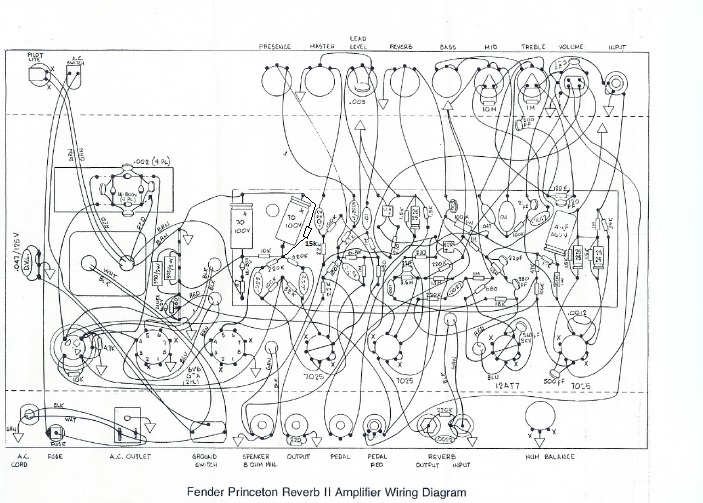
Here's Fender's
wiring diagram. I have made one
correction because in the original, one resistor was
not shown - it's the 15K bias-setting resistor lying beside
the 10/100 electrolytic.
There's a
clearer version here
but without the correction.
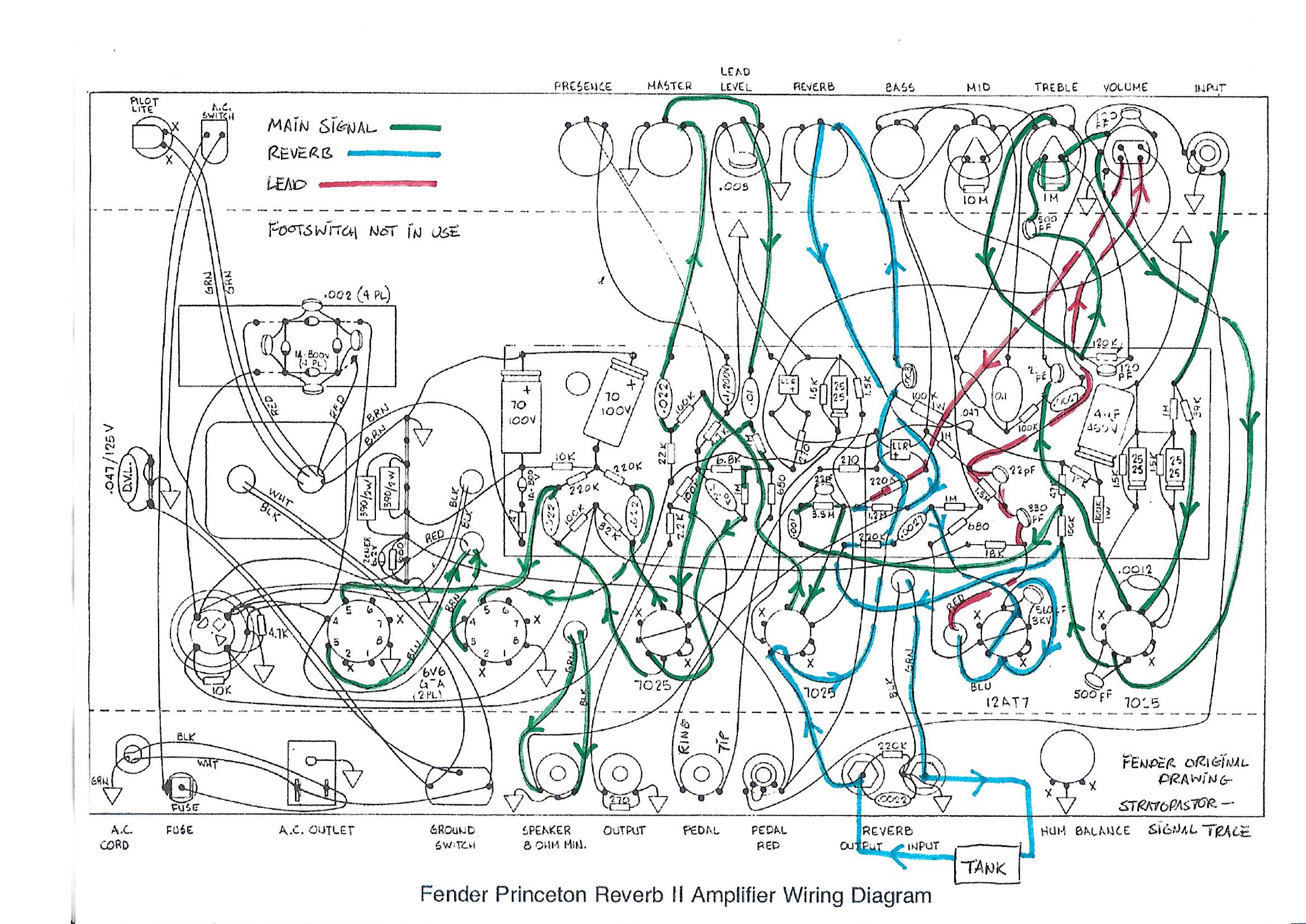
Here is the same wiring
diagram with the signal paths coloured in. Green is the normal
signal path, blue is the reverb circuitry, and red is the
'lead' sound.
Notes
(1) the usual warning about very high voltages and my
disclaimer concerning injury or damage.
(2) I have used green for the signal path before and after the
lead and reverb sounds are combined. If you've got reverb or
lead 'on' then the path shown green will have reverb or lead
sounds in it after that point.
(3) Some paths are different when the footswitch is used. I
have not shown these.
(4) The signal takes three paths through the tone controls. I
have only shown the simplest path, which is through the treble
control. Treble and mid boosts are shown 'off'.
(5) v4 (the fourth valve/tube, counting from the right) is the
phase splitter, so it has 2 wires 'in' and 2 wires 'out',
working in a kind of parallel arrangement, each feeding one of
the 6V6 power valves/tubes.