Modifications to change the TONE
BACK TO MAIN MODIFICATIONS PAGE
INTERIOR
PHOTOS for reference
How
to
dismantle
the
PRII
PRII
home
email me...
SPAMDEFEATstratopastor@hotmail.com
TONE CONTROL
MODS
SPEAKER
DIRECTIVITY
CURE
(JAY
MITCHELL
FOAM
DONUT
-
IT IS KIND-OF A TONE MOD)
FATTER TONE, MORE GAIN - COMMERCIAL
FIRM'S MOD KIT DETAILS
"MORE 3-D AND SWIRL"
REVERB ISSUES
TONE STACK CIRCUIT DESCRIPTION
MORE TOP-END ZING (a little like
blackfacing)
NEW DEC 2011 - UK Amp tech's experiences
IN GENERAL I AM SUSPICIOUS OF MODIFICATIONS and I prefer only to
list mods which have actually been done. I don't like listing
mods of the "I heard from this guy once..." variety. Nor do
I like the attitude which says "no-one at Fender's R&D
knew anything and an amateur with a DMM on his kitchen table is
more likely to get something right...."
As with all the other
pages on my site, the details are believed correct but I won't
take any responsibility for what happens if you attempt them.
Valve/tube amps store lethal voltages even when switched off and
unplugged from the wall, and if you don't know what you're
doing, you can be badly hurt.
Before you try anything concerning tone... experiment with the knobs! I'm embarrassed to report that I owned this amp for 17 years before trying different settings of 'volume' and 'master'. For example - on my amp, v=10 m=3 has less highs compared with v=4 m=10 (which gives roughly the same sound level and little more noise). Up this point I had assumed that it's best to keep volume on 10. (Why? I had already cut that down a little by sometimes using a 12AY7 in v1...). I think the tonal difference is something to do with the centre-tapped volume pot; also the presence control has more effect with the master at a higher setting. All the other numbers are also available - there is no rule which says one of the knobs must be on 10!
If you have tried
any modifications, I would be delighted to hear from you -
even if you're not satisfied with the result, it's useful
information for the rest of us! I'm specially interested if
you've...
TONE CONTROL MODS
akw in Germany tells me
he knows of someone who felt the mid boost is "very heavy
especially on low volume. There is a .0027 uF capacitor in the
tone stack next to the pull pot. A .001 cap would shift the
frequency and make a milder mid shift." ....and (March 04)
see below because Mark confirms this!
After reading this from akw I
played with the Duncan Tone
Stack Calculator and got the following results for
different values of mid boost cap.... (values below are with all
rotary tone controls on "5")
(a) mid boost off gives
a massive dip (-26dB, about 14 dB down from the rest of the
response line) at 500Hz. I imagine this loss of middle in the amp
stage is intentional, and cancelled out by the open-backed 12"
speaker.
(b) mid boost on with
standard cap (0.0027uF =2700pF) flattens the response and
gives a slight hump (-8dB) at 40Hz, which might explain the
thickness of the sound.(NB April 04 this has been
corrected - previously it said 0.027uF which is wrong. Thanks,
Armin)
(c) mid boost on with
0.01uF =10000pF doesn't make much difference from standard
- the 40Hz hump goes down 2dB.
(d) mid boost on with 0.005uF = 5000pF gives a
near-flat line
(e) mid boost on with 0.0025uF = 2500pF gives a curve
midway between (a) and (b); small hump at 20Hz (surely this
frequency is too low to make a difference) and a dip of -16dB at
120Hz. Perhaps a good place to start experimenting.
I haven't changed any of the
tone components on my amp, so the above is theoretical.
---------------------------
Brighter, with more thump
"My tech and I also talked about the 500pf cap on the schematic on valve 1 on the A side between pins 1 & 3 which is intended to control tube oscilations by filtering high frequencies and the .0022uf cap( which was originally in the amp a .0012 but that I change to the .0022 value on the schematic) on the input circuit to the reverb valve between Pin 6 of valve 1 B side and pins 2
& 7 of valve 2. I had a .0015uf at the valve 1 A side location which he changed to a 330pf . He also lowered the value of the .0022uf reverb cap to .0015uf which he said could go to a lower value yet. (NB Armin W points out that this value should be HIGHER to get more bass - somebody experiment and report back?) The amp became a lot brighter overall with a bit more thump.
"Along with all this I previously changed the resistor from the input jack to pin 2 of valve 1 side A from the 37k ohm that was originally installed on the amp to the schematic value of 68k ohm. Dana (the tech) suggests that this resistor can go lower. I may try the 37k ohm again now that the bias is set properly.
"Now with the bias set the valve 1 cap and the reverb input cap change along with the cap change on the mid-boost the amp has much better lead sound with the lead switch pulled and the reverb cranked up without using the pedal. I may modify the pedal so that the reverb changes level when the lead channel is on.
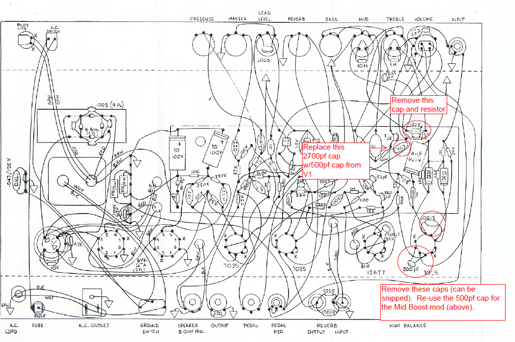
Mid-Boost Cap
"A further note on the mid- boost change. Before with the .0027uf cap there was seemingly no adjustment thru the mid pot when boosted. Now with the .0012uf cap there it is possible to adjust the mid level while boosted. (You can see this mod on Greg G's drawing below)
(Mark concludes) ...I've yet to draw up the circuit for the 3 switch pedal with boost. You will get that ASAP."
---------------------------
Armin W has very kindly sent me the following, still on tone mods.... (April 04)
"Still on the contribution from Mark above ....but another point I think is also a limiting factor: there is a 330pf cap which comes from the primary coil of the reverb trannie to the input (pin 2)of V3B. This should be a 0.001 or higher to get more mids and bass into the
boosted (lead) sound.
The sound on the small Series II amps is based on Rivera's idea to make the preamp free of a certain buzziness (which can be heard in a totally cranked preamp) by blocking deeper frequencies. The result is, it also causes the amp to sound smaller and thinner than it needs to be (this was a part of the 80ies sound - think of Boston, Survivor, Foreigner and so on). To get a more bluesy sound with full mids, you can modify the amp more in the direction of the 1960s blackface specs on certain points.
What you have to do: After the second preamp stage (V1B) on the way to the third stage (V3B) is a 0.001 coupling cap which is blocking lows. To go to the sixties specs, change to a 0.01 or higher. This might be a big step."
I have done this mod - it didn't seem to make much difference, but I left it in place.
(Earl K tried this on his, and emails me....
"it just sounds better. my highs arent as loud but more chimey." Thanks Earl!) Armin continues...
"Rivera also used a 0.047 cap as mid cap in the tone stack. With a .015 you can bring up the low mids to get a fuller sound."
-------------
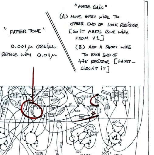
PROFESSIONAL MOD COMPANY'S "FATTER TONE, MORE GAIN" MOD
There's a firm who sell mod kits for various amps. They sell one for the PRII which makes the bias measurable and adjustable from outside the amp. When you buy this kit, they include a "fatter tone, more gain" kit as an added extra. A couple of times a year, people ask me if I know what's in this extra kit. Well now I know, so here you are. It's a kind-of combination of Armin W's second mod (see above) plus a small change to Martin Kuhn's mod 5 (on the gain mods page). The "fatter tone" refers only to the clean sound, not the 'lead' sound.
I did the 'fatter tone' part of this mod and really didn't hear much difference, so eventually I took the extra cap out again. However I have been in touch with someone else who said it really made a big difference.
I have redrawn this mod on the Fender wiring diagram. Really this is 2 mods which do not depend on each other. For "fatter tone" do the cap change (that's Armin's mod, shown on the left here) and for 'more gain' do the 2 steps on the right (a little like Martin's mod 5).
I hope this is clear enough - it shows the right-hand end (input end) of the circuit board with the valves/tubes nearest you.
REVERB ISSUES

MOUNT THE TANK IN THE BASE, NOT ON THE SIDE

Fender only used one model of reverb tank on the PRII - the Accutronics 8AB3C1B. The last 'B' indicates it should be mounted in the base of the amp, open side down. In many PRIIs, Fender screwed this tank to the side of the cabinet - the right-hand side when looking at the back of the amp. After 16 years of me wondering why, I had an eBay seller point out that the factory-upgrade EV speaker is too big to allow the reverb tank to go in the base. So, since they probably fitted the tank before deciding which speaker was going in there, it would have saved time and trouble to put the tank on the side. Why then, I hear you ask, did they not buy tanks which were specified for vertical mounting? Aha, I reply, the same tank was used in 2 other amps and they would have lost the economies of scale. It's still just a theory, but there you go.

If your PRII has the tank on the side wall and doesn't have the EV or some other speaker with an oversized basket or magnet, try standing the amp on its side (with the reverb tank nearest the floor). After a few minutes for the springs to settle, I think you will find it improves the reverb sound. If you like what you hear, move the tank to the base of the amp -  it only takes 5 minutes, a cross-head screwdriver and something with a sharp point to start new screw-holes in the wood.

MUSHY REVERB - NO USE ABOVE 3 OR 4

This is everyone's complaint. Turn up the reverb above 3 or 4 and the reverb sound goes to mush. I think the springs are overdriven. My cure is to use a 12AU7 instead of a 12AT7 in the second valve/tube position; it gives me useful amounts of reverb all the way up to 10. The lower gain also affects the 'lead' sound - it reduces it from 'distorted' to a kind of 'fat boost'. Soren A on our Facebook Group say, change the reverb pot from 100K linear to 100K log. I haven't tried this myself.
"There's
a lot going on in that area of the circuit. They were
obviously really trying to enhance the tone.
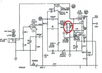
"Like the common BF and SF Fender tone stack, the Treble
control acts as a balance control for the highs and the
lows. On the schemo I have, there is an error: the 100k
should be shown connected to the plate of the tube and the
250pf. (I have changed this on the copies shown on my
websites - Stratopastor.)The signal is split there;
the highs like to go through the 250pf to the 'upper' leg of
the treb pot, the lows are resisted there due to that small
250p cap. The lows however more easily go thru the 100k
slope resistor than the highs and divide up between .1 bass
cap and .047 mid cap, and get drained off to ground
according to the position of the bass and mid pot. The highs
don't like to go through resistors as easily as lows, so
they are attenuated slightly. If the mid and bass pots are
set high, then more of the signal gets put on the 'lower'
leg of the treb pot. Thus explaining the standard Fender
tone stack and why the treb is a balance pot between highs
and lows. So now, all the signal is coming out of the wiper
of the treb pot, and sent to the vol pot via a network of
caps and res, where more is happening that you don't
normally see on a Fender tone stack.
"The volume pot is center-tapped. When the volume is at half
way, max highs through the 120p and 100p are sent direct to
it, less if it's on either side of half way. Signal is sent
thru the 820k slightly attenuated in the highs again due to
the resistor, and goes to the upper leg of the vol pot. The
820k resistor in series with vol pot also loses some volume
at the top of the vol pot, and remember some of the highs
are already held back in addition cuz of that 820k res.
"Now you have another leg going thru the 500p and the 1m,
the one meg is shorted out when the push switch on the treb
is closed effectively putting the 500p direct to the top of
the vol pot, so when the vol is dimed there is a direct line
from the treb pot thru the 500p (the 500p holds back the
lows from getting thru) to the top of the vol pot.
"So there should be an apparent tone shift through the range
of the vol pot.
"There is a circuit to bypass the 250p treb cap which adds
more mids.
"The 'standard' thing Fender did (not on This amp tho') is
to put a (sometimes switchable) bright cap on the vol pot,
which lets you regain the highs lost through the resistance
of the vol pot when it is at low levels. Once you get past 5
it has less and less effect, til at 10 on the vol you hear
no diff.
That help?
MORE CLASSIC CHIMEY FENDERY ZING - really easy mod....

Having read on The Gear Page that you can get the Rivera-era Concert closer to the classic 60s Fender sound, I tried it on my PRII (March 2011) and it does have a subtle but good effect in my opinion. This mod is part of the process known as "Blackfacing", in which a silverface amp is modified to sound more like its earlier, blackface equivalent. You can't really blackface a Rivera-era amp -they're too different from anything that came before - but I like this mod. Jan 2014, Greg Gagliano also recommends it (see above).

Theory - The Rivera-era Fender design team added tiny capacitors to their preamp valves to make absolutely sure the amps wouldn't suffer from oscillation or interference. Called "snubber caps", their side-effect was to remove a little of the top end and make the amp sound slightly sterile compared to the classic Blackface designs of the mid-1960s. This mod takes these caps out of circuit. There are two in the PRII - one for v1a and one for v1b, shown on the schematic as wired from pin 1 to pin 3, and from pin 6 to pin 8; each on the + side of the 25/25 cathode cap. They are both shown on the schematic as 500pF caps, but on the wiring diagram and in real life the v1a cap is 0.0012uF (=1200pF).

Practice - After dismantling, find the socket for v1 (the tube/valve socket nearest the input end of the amp). It has 2 small capacitors actually mounted on the valve socket. For each capacitor, cut one leg close to the solder joint, and bend away/tape up the now-free leg-end so that it can't short against anything. Connect the speaker and a guitar, CAREFULLY switch on the amp and listen for extra noise, radio interference etc. If all is well and you like the small amount of high-end treble you've just gained, that's all you have to do; switch off, disconnect from power, reassemble. Otherwise switch off, disconnect from power, pull v1 out of the socket, re-solder the caps, reassemble.


Dec 2011; Notes from a UK Amp Tech

I've had two PRII owners in the London area recommend Steve Dove of S.A. Ampworks. Here's a note Steve sent to me in 2010 concerning some mod work done to a PRII which had turned up for sale some time after he had modded it;

"Hello Andrew... this is one amp i will not forget in a hurry. I was asked appr 5 yrs or so ago to give this amp some boogie characteristics. The owner said he was somewhat disappointed with the basic amp, my brief was to make this a portable powerhouse with a great clean sound, and there started the challenge, and that it certainly was. First thing I modded for 6L6 use and this takes the power up to in the region of 35 watts and with some other improvements this sorted the output section,then I turned my attention to the preamp, I felt that the amp just sounded wrong, I was convinced there was a lot to be had from this one, I revoiced the preamp as far as the clean path was concerned, and got that to sound really nice, especially with some volume. The overdrive I found was utterly horrible - I actually think that whoever devised the configuration here,and that applies to all the amps in this series, it was just so poor in conception... my mods gave the amp more gain and took away the inherrent muddiness. I worked on the overdrive aspect over a long period,and with the restrictions re cost I think that a very good end result was the end product. I would like to have fitted another control to open the gain up and make that more versatile, and one or two other features,but the thing with this amp,when it was turned up some, it would sing. A little thin with the vol down, but (customer's name) loved it for use at his performing levels. I hope some of this is of interest, I learned a lot about this type of amp during the time I had it. Regards, Steve."

You will note Steve's not giving away much detail here, which is understandable because this is how he makes a living! Also I haven't dealt with him personally apart from a friendly exchange of emails... however he seems to know what he's talking about and I gladly link to his website.