RELIABILITY MODIFICATIONS
INTERIOR
PHOTOS for reference
BACK TO MAIN MODIFICATIONS PAGE
PRII
home
last update March 2016 - cooling fan
email me...
SPAMDEFEATstratopastor@hotmail.com
IN GENERAL I AM SUSPICIOUS OF MODIFICATIONS and I prefer only to
include mods which have actually been done. I don't like mods of
the "I heard from this guy once..." variety. Nor do I like
the attitude which says "no-one at Fender's R&D knew anything
and an amateur with a DMM on his kitchen table is more likely to
do better...."
As with all the other
pages on my site, the details are believed correct but I won't
take any responsibility for what happens if you attempt them.
Valve/tube amps store lethal voltages even when switched off and
unplugged from the wall, and if you don't know what you're
doing, you can be badly hurt.
If you have tried any modifications, I would be delighted to hear from you - even if you're not satisfied with the result, it's useful information for the rest of us! I'm specially interested if you've converted to cathode bias, converted to tube (valve) rectification, or added a sag resistor.
RELIABILITY MODS (I have done these)
Big thanks to John Philips for telling me about these mods. He's an experienced guitar tech, near Edinburgh in Scotland.
All the time I’m describing
the works, I’m looking down into the works, standing with the
chassis front panel close to my tummy and the row of valve sockets
(we’re looking at the ‘wires’ end of those, not the ‘valve’ side)
running along the far edge of the chassis. The output valve
sockets are the last 2 on the right. Everything we’re going
to be playing with is on those 2 sockets, or on the end of wiring
board near those sockets.
1 Uprating the Bias Feed resistor
After dismantling, this takes
5 minutes, costs 25p (35 cents US), and could save a lost gig and
a trip to the tech.
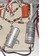
See the little resistor in the top right hand corner of the photo? (To the right of the orange capacitor). It's 47 ohms, which is correct, but the wattage isn't big enough on some models - in other words it's on the limit of how much heat it can dump to the air, with the result that it could overheat. As Unquiet predicted, mine was badly discoloured from overheating. Trouble is, this resistor has been overheated 'n' mistreated for so long that it's become mean, and if it's goin' down, it's takin' something else with it - namely, the output valves (tubes). The bias supply comes through this resistor, and if the bias supply fails, there's nothing to restrain the valves from running at a very high idling current, which they probably won't take for very long.
One guy emailed me to say
that when he touched this resistor, it turned to dust
instantly. Amazing that the amp had worked up to that point.
You can tell if the
bias feed resistor has failed without going inside the amp
because if it has died, (in addition to there being no sound or
very distorted sound), there won't be any -6.2V supply to the
footswitch. Remove the power valves - if the bias feed resistor
has died, the valves might also be dead now, but maybe they're
still OK and you don't want to stress them any more while running
these tests. If you have a footswitch and the LEDs won't light,
that points to the death of the bias feed resistor. If you don't
have a footswitch, push a stereo jack plug into the red f/s socket
- there should be -6.2V from the tip connection to ground. If
there's no voltage, the bias feed resistor's probably dead.
The solution is to
replace it with a 47 ohm resistor, one watt or bigger.
More than one watt is OK too, but much more might be too big
physically. Took me less than 5 minutes, not counting the trip to
my local component shop, and dismantling time. Be careful not to
overheat the diode next door while soldering.
AFTER
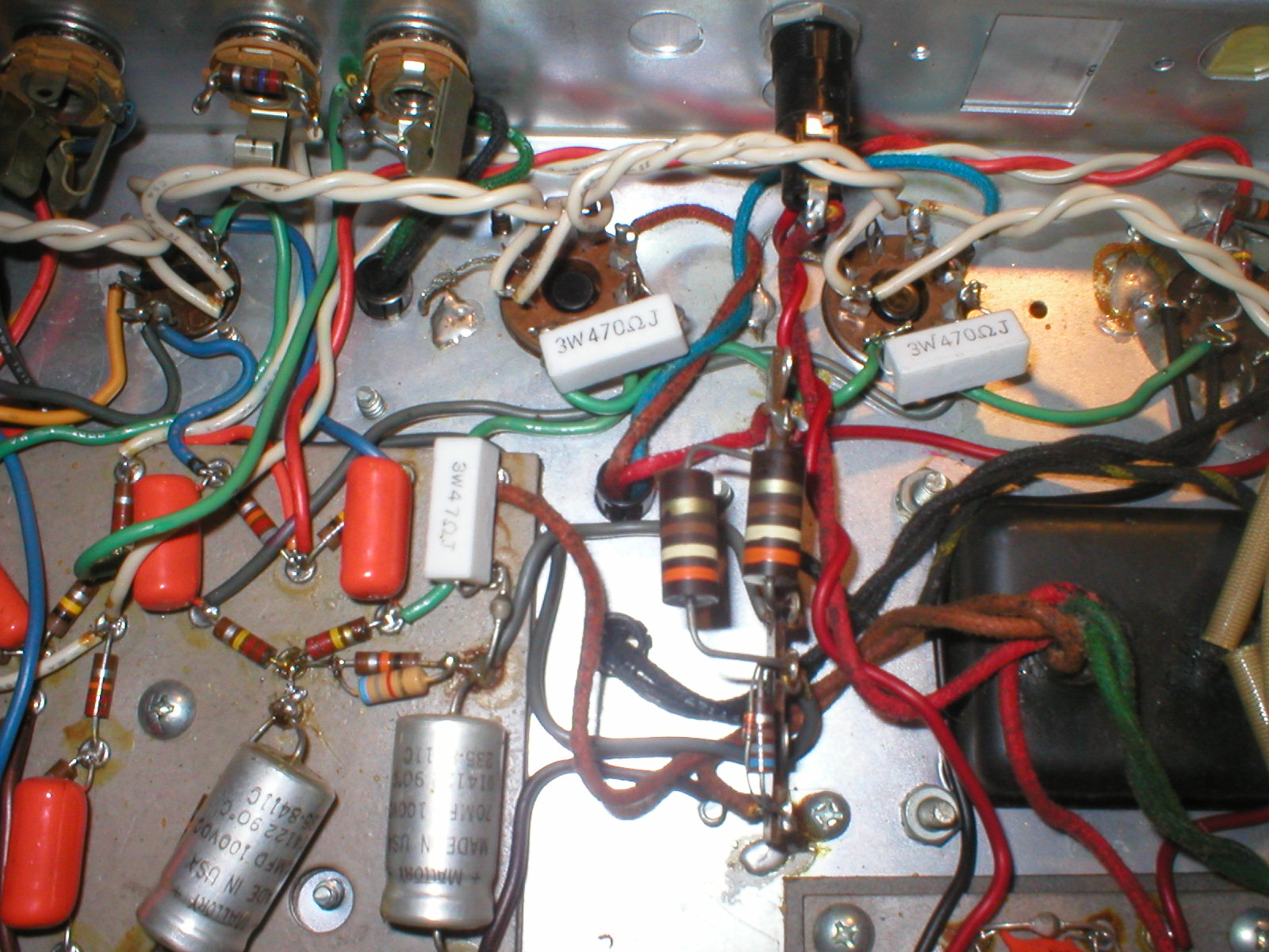
In my photo above, the new bias feed resistor is the white
rectangular component beside the orange capacitor. The new
screen-grid resistors (see mod below) are the white "3W470ohmJ",
one on each power valve socket. Photo is my
copyright.
2nd reliability mod; Fitting Screen-Grid Resistors
This takes 10 minutes once you're inside. And two resistors, each costing 25p. The photo above shows the finished mod.
The idea is to insert a 470-ohm 2 watt wirewound resistor in the wire running to pin 4 on each output valve (V5 and V6, 6V6GTA). Why? John Philips writes....
The screen-grid resistors prevent the tube grids drawing as much current under heavy load, and also make sure they remain at lower potential than the plates. Under very heavy tube loads, the plate voltage can actually drop below the screen grid if no resistors are fitted, which results in a massive increase in screen grid current (because it begins to act as a secondary plate) and very shortened tube life, or even sudden failure. I don't know why Fender didn't fit them to all their amps - the larger amps all have them......
see here for a drawing of the solder tags as found inside the chassis.
I've done this one too. Pin 6
on each power valve socket is unused (pin 6 goes nowhere in the
valve) so it's available as a handy solder mounting tag. Remove
both power valves from sockets. All the wires you're going to move
are probably green. On V6 (nearest the end of the amp), pin 4 has
2 wires. Unsolder them from pin 4 and resolder them to pin
6. Solder the new resistor to pin 4 and pin 6. Keep the resistor
leads short so it can't vibrate too much. On V5 pin 4 has only one
wire (it comes from V6). Unsolder the wire, solder it to pin 6,
solder the other new resistor from pin 4 and pin 6. Replace the
valves. Job done.
Since doing this mod, I've
noticed that the amp's bass response seems better in a way
that's hard to describe. It's like there's less wasted effort, or
more energy focussed in the right place. The bottom end cuts
through the band more clearly and there's no added 'boom'. This
didn't show up when playing quietly at home. Your experience may
be different.
Mark from Cleveland, Ohio, USA, kindly wrote up some of the component-level changes he's done with his amp tech;

"I installed screen grid resistors (see reliability mods above). Definite sound improvement. My tech checked to see if doing so affected the bias setting so I could play around with different screen grid resistor values below 470ohm. The change in bias settings between with or without the resistors is only  a few hundredths of a milliamp which is insignificant. But the amp sounds so good now I may not try any other values.

3rd Reliability Mod (I haven't done this yet) - May 2022

I am grateful to Dirk Buffel in Belgium, who has noticed that the 4700 ohm 1/2W resistor on the cap can has 55V across it (schematic values) which calculates to 0.64W. In the amp he was working on, this resistor was discoloured by the heat and measured only 1700 ohms, resulting in an increased plate voltage in the preamp. This resistor should be replaced with 4700 ohms 1 Watt.
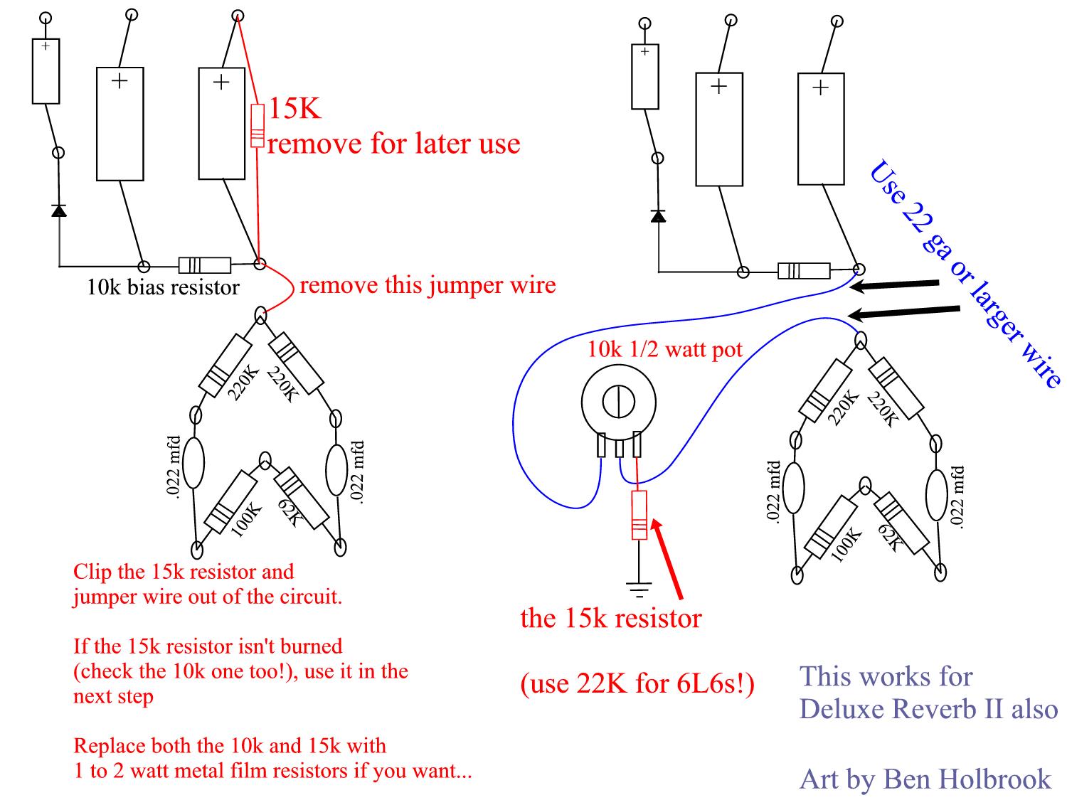
This is from Ben Holbrook -
thanks, Ben. It also applies to the Deluxe Reverb II. I haven't
done this one.
The point is make the
bias adjustable by means of a pot mounted inside the chassis. (You
still have to get inside each time you adjust the bias, and you
still have to do all the measurements on my 'bias' page, but you
only have to turn a knob instead of soldering and resoldering
resistors in place.)
This mod is reversible.
Extra parts needed
- one potentiometer, 10K, linear, 1/2 watt.
- some insulated copper wire, 22 gauge or
thicker
- silicon / sealant glue
Note a 22k resistor is needed if you're using 6L6 power tubes. See
'Getting
louder' for the pros and cons of using 6L6s....
Diagrams and photo are by Ben
himself (I haven't checked them).
---------------------------
Standby Switch

In response to a request by email, I worked out this method for installing a standby switch. My friend at the other end said it worked. I should add that I haven't done this myself, and to be honest I don't think it adds anything of value. (Feb 2012 ... this link makes a lot of sense to me, explaining why you don't need a standby switch...)

But, here's my write-up....

"working off the schematic and some interior photos, it looks to me like you want the standby switch to interrupt the B+ supply (around 420V DV, be very careful) after the first cap and before the choke. That's where other Fender amps have standby switches.

Drain the caps before starting work if you don't want a jolt that'll throw you across the room.

Follow this on your amp; inside the amp, just behind the front panel logo "Princeton Reverb II" there's a small panel with 4 diodes in a square formation, surrounded by 4 circular flat capacitors. 2 red wires head off to the power transformer. Ignore these. One wire, I think it's the black one, goes to ground. Please check this. The other one is the path we're following. I think it's pink or red. This is the 420V DC line. It heads off to the cap can -  the aluminium tube sticking out of the chassis at the nearby rear corner. At the same place the red/pink wire arrives at the cap can, it looks like there's a black wire (please check this) running off to the choke, which is the small transformer-like component next door to the power transformer on the outside of the chassis. (There's another black wire running back from the choke, almost to the same spot). It's that first black wire you need to unsolder. Call the place where it was soldered to, point A. Don't lose sight of that terminal. Unthread the now-loose black wire from its original path; this is going to one terminal of your new switch. Solder a new insulated wire to point A. This will go to the other terminal of your new switch.

The new switch needs to be single pole single throw (SPST) with a rating of 500VDC or more (never mind the lower AC rating... you need 500VDC or more). It will have 2 solder terminals. Solder the 2 wires mentioned above to the switch, one wire to each terminal, doesn't matter which way around.

Seems to me a standby switch is most useful on the front panel, but I personally wouldn't drill a hole there as it will reduce the value of the amp. But it's up to you.

In operation you'll switch the amp on with its original power switch. The red light will come on and the tubes will begin to glow but the amp won't work until you switch the new standby switch to on.

This whole procedure is guesswork based on photos and I have not opened my amp to verify it. Please check my logic every step of the way. I must emphasise that you will be playing with the lethal-voltage part of the amp and you will be doing all this work at your own risk. Happy to field questions though."

Theory
A standby switch fitted to many valve/tube amps, allows the tubes to warm up or remain hot but switches the high-voltage DC supply on or off. So you can warm up the amp before switching on the DC; some say this prolongs the life of the tubes by avoiding 'cathode stripping'. Also you can 'mute' the amp without allowing the tubes to cool, which probably is less stressful to the tubes than switching the entire amp off.
back
to top
PRII
home
BACK
TO
MAIN
MODIFICATIONS PAGE
rebiasing
dismantling