Fender
Princeton Reverb II
Reference
Photos
last update May 10
modifications
page
Here
are
some photos of Princeton Reverb IIs which may help you
with a project or troubleshooting. The
schematic,
parts
list
and wiring diagram are here.
I
have
begged, borrowed or stolen these photos of the Princeton Reverb
II over
several years, If you see your photo here and would like credit
OR the
removal of the photo, please email me and I'll do as you ask.
This is a US (110V) PRII.... 220v owners,
see the other photos
In this photo, the rear panel components are (left to
right);
hum balance, reverb input, reverb output, pedal red, pedal
(plain),
line/recording, speaker out, ground switch, courtesy outlet,
fuse,
power cable entry.
The sockets are (left to right) v1,2,3,4,5,6,cap can.
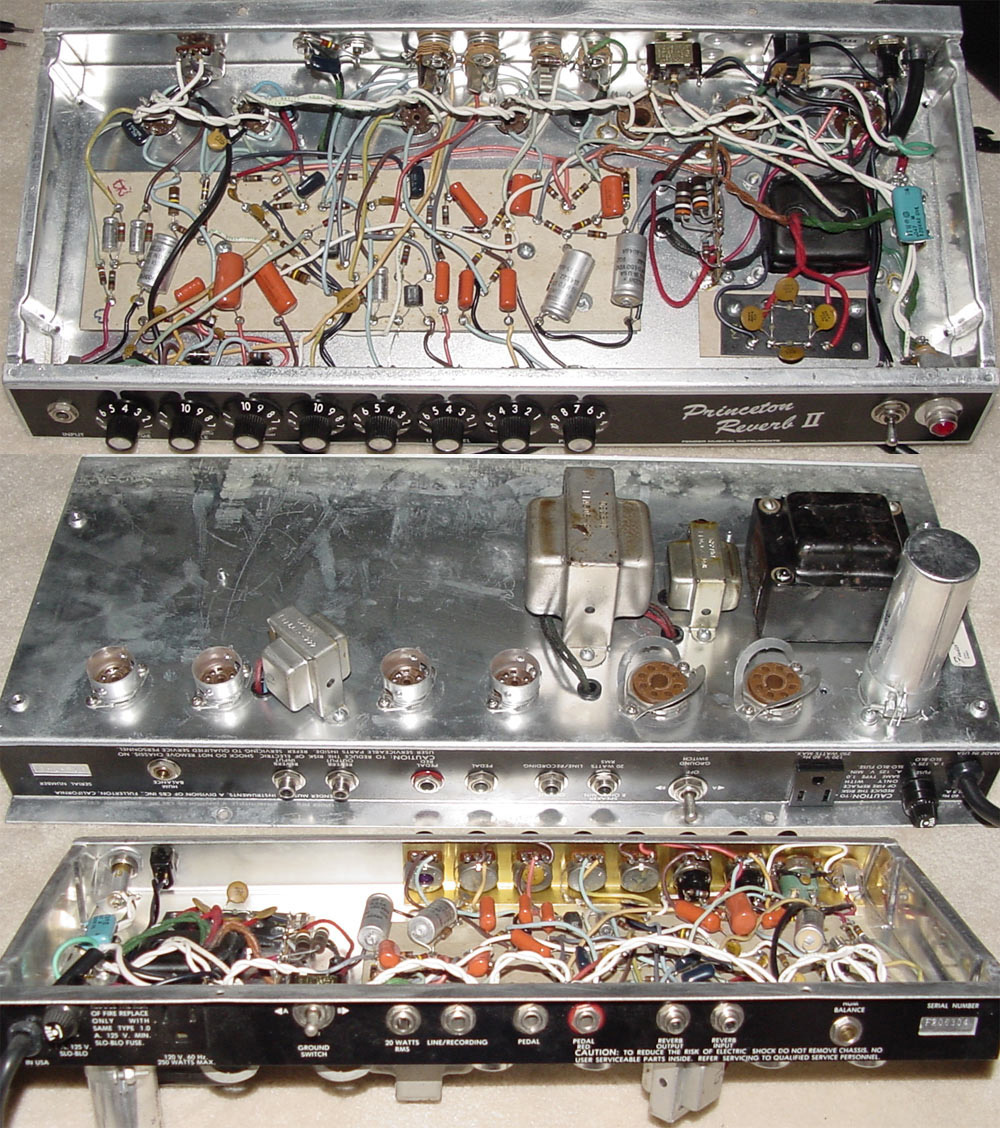
in
the
photo above note the 'ground switch' and, to the left of that,
the
"courtesy outlet". These do not appear on the 220V models.
220V model shown below...
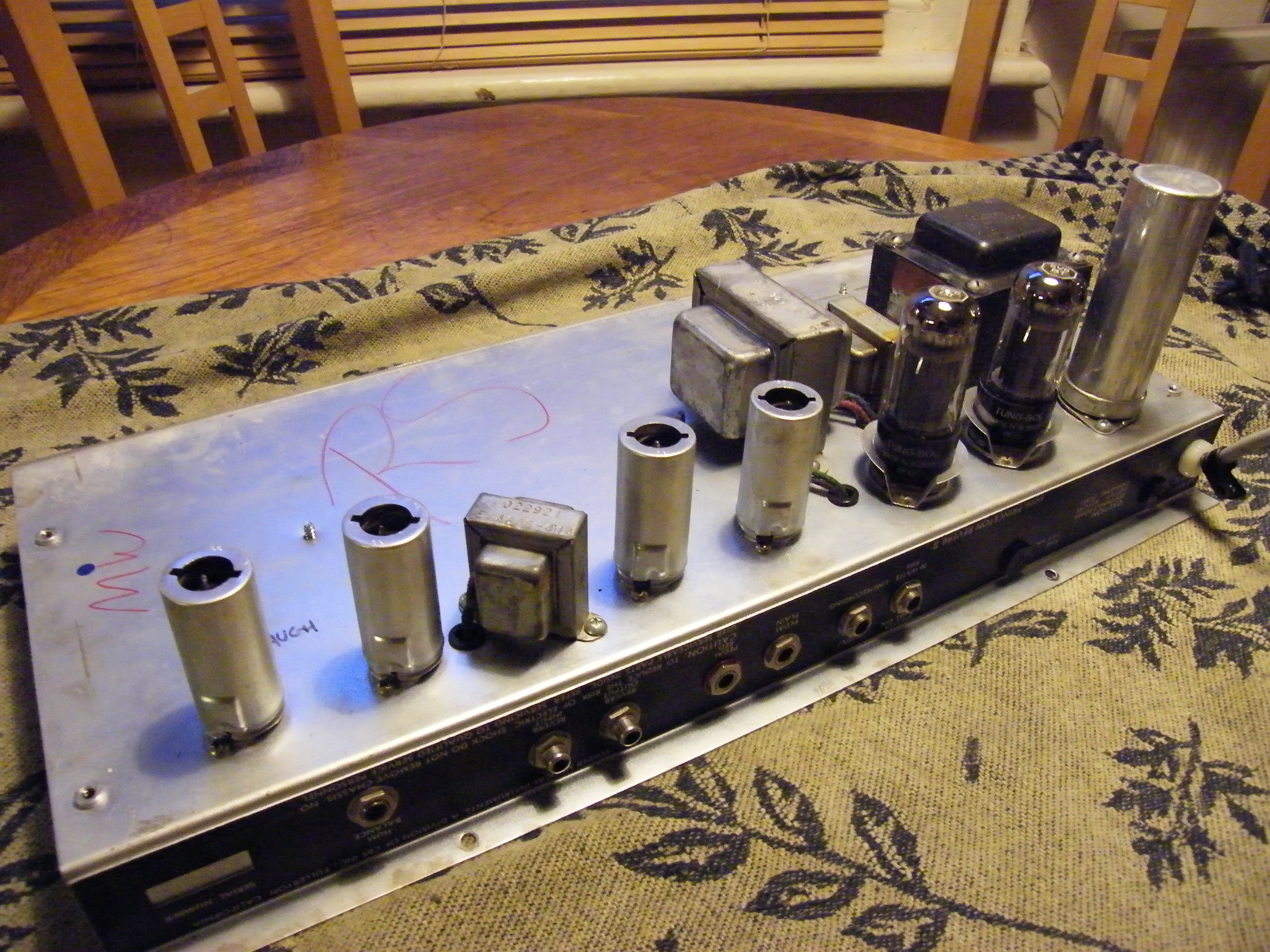 above - 220V model with the valves (tubes) in place. Valves
are
(left to right) v1,2,3,4 with metal covers in place, v5 and v6.
Transformers are (left to right) reverb transformer, output
transformer, choke, and power transformer. The cap can is
extreme
right.
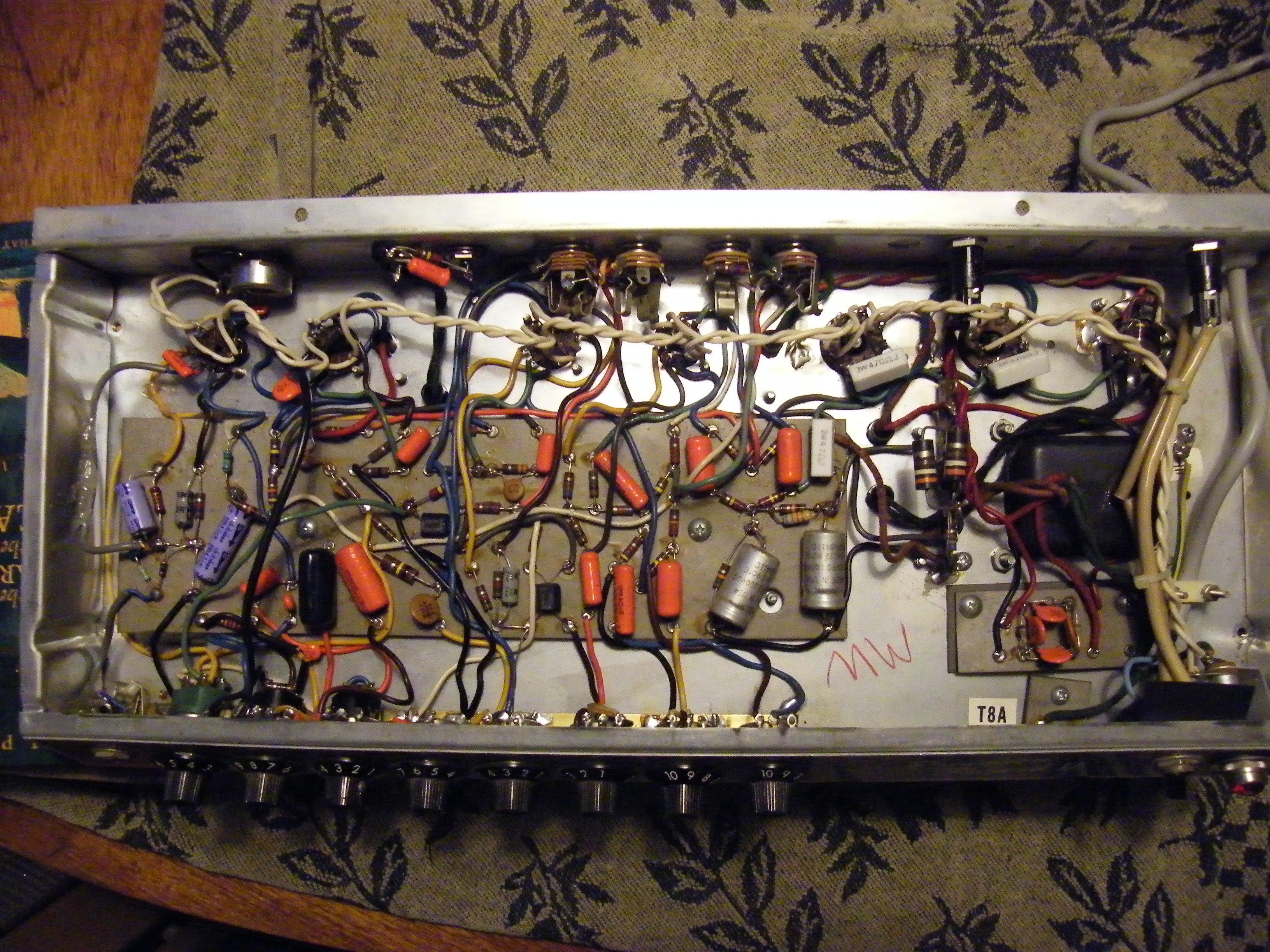
below - same 220V model, interior
note (1) at the top right-hand corner of the circuit board
there's a new,
grey
rectangular 47 ohm bias feed resistor (2) down from that,
there's
an extra resistor in parallel with the original resistor to'cool'
the power valve bias (3) both power valve sockets have
grey
rectangular 470
ohm
screen-grid resistors (not present in unmodified amps) (4)
the
purple capacitors on the left-hand side (input side) are
non-original.
Any other differences in component colours (compared to the 110V
circuit board) are coincidental and not because of the 110V/220V
difference.
above - 220V model with the valves (tubes) in place. Valves
are
(left to right) v1,2,3,4 with metal covers in place, v5 and v6.
Transformers are (left to right) reverb transformer, output
transformer, choke, and power transformer. The cap can is
extreme
right.
below - same 220V model, interior
note (1) at the top right-hand corner of the circuit board
there's a new,
grey
rectangular 47 ohm bias feed resistor (2) down from that,
there's
an extra resistor in parallel with the original resistor to'cool'
the power valve bias (3) both power valve sockets have
grey
rectangular 470
ohm
screen-grid resistors (not present in unmodified amps) (4)
the
purple capacitors on the left-hand side (input side) are
non-original.
Any other differences in component colours (compared to the 110V
circuit board) are coincidental and not because of the 110V/220V
difference.
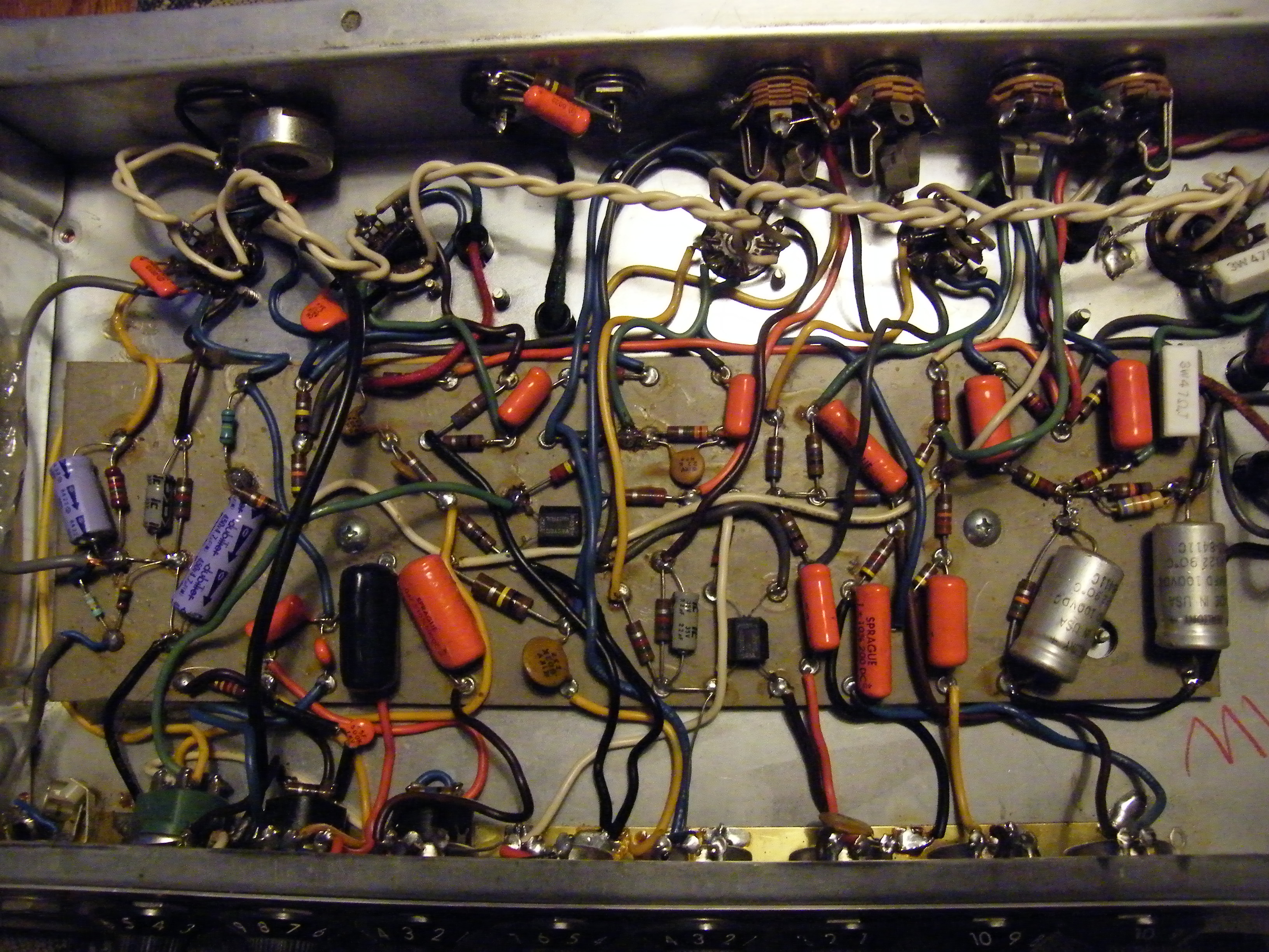
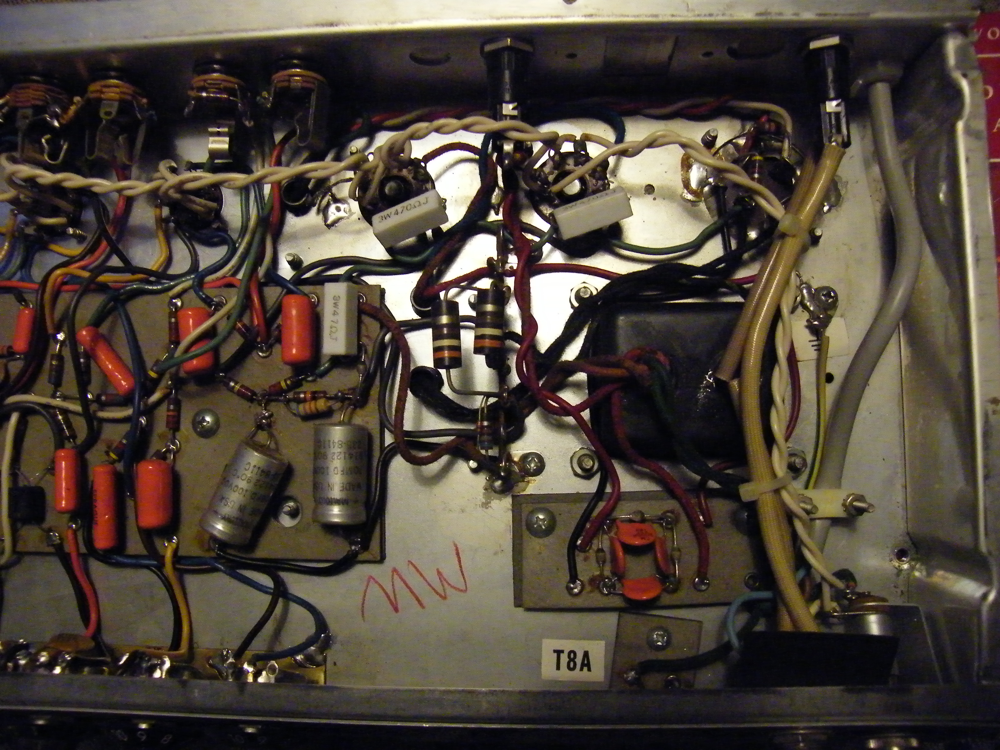
 below- same 220V model, input end
;
note (1)
at
the top right-hand corner of the circuit board there's a new,
grey
rectangular 47 ohm bias feed resistor (2) down from that,
there's
an extra resistor in parallel with the original resistor to'cool'
the power valve bias (3) both power valve sockets have
grey
rectangular 470
ohm
screen-grid resistors (not present in unmodified amps) (4)
the
purple capacitors on the left-hand side (input side) are
non-original.
 above - 220V model, input end
below- same 220V model, output end
above - 220V model, input end
below- same 220V model, output end;
US
owners,
in this photo you can see the rectangular blank where the
courtesy
outlet should be on your amp's rear panel.
See
the
photo at the top of this page for a 110V model
with
the courtesy outlet and ground switch.
 above- 220V model, output end
 -
note (1) at
the
top right-hand corner of the circuit board there's a new,
grey
rectangular 47 ohm bias feed resistor (2) down from that,
there's
an extra resistor in parallel with the original resistor to'cool'
the power valve bias (3) both power valve sockets have
grey
rectangular 470
ohm
screen-grid resistors (not present in unmodified amps).
PRII
home
email me... (remove the capitals)
NOSPAMstratopastor@hotmail.com