Fender
Princeton Reverb II
Modifications - Gain, Distortion, Volume
for mods to the tone of
the
amp see
here
BACK TO MAIN MODIFICATIONS PAGE
PRII
home
dismantling
INTERIOR
PHOTOS for reference
email me...
SPAMDEFEATstratopastor@hotmail.com
WORLD'S EASIEST OVERDRIVE MOD
GETTING
35 watts
MORE CLEAN VOLUME
MORE GAIN SRV-STYLE
FATTER TONE, MORE GAIN -
COMMERCIAL FIRM'S MOD KIT DETAILS
USE OF POWER ATTENUATOR
LOOSER, MORE ORGANIC SOUND (NFB MOD)
IN GENERAL I AM SUSPICIOUS OF MODIFICATIONS and I prefer only to
list mods which have actually been done. I don't like listing mods
of the "I heard from this guy once..." variety. Nor do I
like the attitude which says "Fender's R&D knew nothing, and
an amateur with a DMM on his kitchen table is more likely to get
something right...."
As with all the other
pages on my site, the details are believed correct but I won't
take any responsibility for what happens if you attempt them.
Valve/tube amps store lethal voltages even when switched off and
unplugged from the wall, and if you don't know what you're
doing, you can be badly hurt.
If you have tried
any modifications, I would be delighted to hear from you -
even if you're not satisfied with the result, it's useful
information for the rest of us! I'm specially interested if
you've converted your PRII to
cathode bias, or to tube (valve)
rectification, or added a sag resistor.
EASIEST WAY TO GET BETTER CLEAN SOUND; CHANGE VALVES
(TUBES)
You can use different preamp
valves to reduce the gain in your amp, which might make for a
clearer clean sound. If you're already happy with the clean sound,
you can stop reading now, but if you're convinced that the sound
is just a little overdriven no matter what you adjust, then you
could try putting a lower-gain valve in position 1, 3 or 4 - most
likely position 1 (nearest the input end of the amp, the
right-hand side viewed from the
back). If the usual 12AX7 (7025, ECC83) has a gain of
100, then on that scale a 12AT7 is 70, 12AY7 is 40 and 12AU7 is
20. I use an Electro-Harmonix 12AY7 in position 1 - the 12AY7 is
the original front-end valve in the 1950s "tweed" Fender amps.
The difference is, you're
sending less signal through the preamp stage of the amp. To get
the same volume as before you'll find you have to turn the master
volume knob up to a higher number than before. And the amp will
have less absolute-maximum volume than before. (Note, this will
NOT give you "cleaner and louder"... the only way to increase your
max.clean volume, as perceived by the audience, is to make serious
changes to the power stage, or get a bigger amp.)
Anyway, fitting a lower-gain
valve is cheap, non-invasive and takes only 5 minutes to find out
if you like it or not. (Even if you don't like it, the 12AY7 is an
acceptable emergency spare for v1,v3 or v4.) I think only
Electro-Harmonix make the 12AY7 right now (12 or 13 pounds in the
UK, 12 dollars US (March 2011)), though you can buy unused
ones in the older, more expensive brands.
WORLD'S EASIEST GAIN MOD
March 2022 - I thank 'Stephen'
for emailing me to tell me something obvious, something which has
worked on other amps, and I'm embarrassed I didn't think of it.
Use one of the reverb cables to connect the 2 rear-panel RCA
reverb connectors direct to each other. You will of course lose
the reverb, but there are effects pedals for that. The reverb knob
is now an extra overdrive control, fading in an overdrive which is
produced differently to the original 'lead' sound. If you use a
footswitch, you can turn this new overdrive on and off with the
reverb footswitch. You might like the quality of this overdrive...
you might not... but it's easily reversible.
LOUDER: GETTING 35W
Pat Morford (BC, Canada)
writes....
"my amp has been modded to use
6L6 type output tubes. this is a HUGE DIFFERENCE, as the entire
interplay of the amp circuits change for the better...the output
transformer and power supply sweet spot is PERFECT with the
simple mod, and speaker change, with the right tubes. This is a
very simple bias mod, and I have been running it flat out for
hours, the transformer is WELL within heat range, same with the
output transformer.. this is a full 35 watt amp now... I
will attempt to map the changes to the bias circuit, it's
probably ONE RESISTOR only." (Pat is right, you can use
the rebiasing
method
on
this
website and it will involve only one resistor value, but
with 6L6s all the target numbers will be different to 6V6 operation. The static
dissipation wattage for 6L6s, and the rough-guide cathode current
range, will be on the web somewhere - good luck.)
I emailed Pat (June 03) and,
while he didn't have time to write this up, he confirmed that (a)
his amp still hadn't melted (b) it's simply a case of fitting a
matched pair of 6L6's and rebiasing.
But for longterm operation
there's more to it. John Philips says it's vital to add the
screen-grid resistors with 6L6s; also that the speaker impedance
requirement changes to 4ohms due to the difference in plate load
requirement. I have had this confirmed by another tech (July 06).
My guess is that, while Fender output transformers can usually
stand a factor-of-two mismatch in speaker impedance, it's asking
too much to have the mismatch AND pull 35W from a transformer
designed for 22W. It's been said on the Weber Amps board that 6L6s
develop a higher voltage across the cathode bypass capacitor (the
25V/25uFs) and these should be replaced with 50V. That was
referring to a Champ, but the principle probably applies here too.
Pat seems to know what he's
talking about, but this mod comes with no guarantees from me or him. I
believe the PRII to be loud enough at 22W. If I wanted a 2 x 6L6 amp I'd go out and get
one..
back to top
-------------


MORE CLEAN VOLUME (see mod 5 below)
MORE GAIN ON LEAD CHANNEL, SRV-STYLE) (see mods 1-4)

Martin Kuhn lives in Jarna, about 30Km south of Stockholm in Sweden - NOSPAMTHANKSmartin.kuhn@telia.com (delete the capital letters). He builds and design amps, and does repairs and mods as a hobby.

Martin writes, in excellent English....

"Last week (Dec 04) a guy came in with a PR II in excellent condition. He wanted it to have more juice, more of a SRV-sound (everybody wants to sound like SRV, right? ) This amp has lots of juice hidden in it! There is lots of gain that is just thrown away between the stages, so one has plenty of room for tweaking the circuit, and turn it into a high-gain monster if you like.

It is basically the same circuit as the mighty Trainwreck (which basically is a Fender with an extra gain stage), plus the reverb! The mods are presented in the attached schematic, feel free to publish them on your website.

All I can say about this mod is that it is kind of an experiment, and a place to start to investigate this circuit. The sound is much more powerful, and you can easily push the amp into poweramp-distortion with a Strat. It gets much more touch-sensitive.

The (unmodified) lead sound sounded just horrible to my ears, I wonder if anybody uses it at all. After the mod it is quite useful, and can be further tweaked to one's taste. You can easily get lots of sustain, and get the amp to sing and the tone to transform into singing harmonics.

Both the customer and I, after trying out different speakers, felt that the Celestion G12H 30 really made the amp bloom".

Here is Martin's very helpful schematic with the mods, and his notes at the bottom, shown in red. I have not tried this mod myself.  Here are some extra notes which Martin emailed to me.

Mod 1 - the main point here is to replace the original cap with a plastic one for better tone and clarity. Martin used 47pF because he didn't have a 22pF in plastic.
Mod 2 - see the notes in red - those resistor values are in kohms, not ohms. This mod reduces the signal for better balance and clarity.
Mod 3 - reduces down the signal, and cuts bass, for less mush, more definition and improved harmonic balance. Whatever value you choose here, plastic caps will improve the tone.
Mod 4 affects clean AND lead.
Mod 5 was not done - it's just an idea - but increasing the original 47K resistor should give more clean volume; increasing it further will introduce overdrive. Any changes here will mean new values for the other mods to get the levels right.
(New
Oct 07; My esteemed correspondent Al Z says he has done Mod 5, but
"installed a 50K pot in series with the 47K resistor so now I
could dial in the "strength" of the clean sound to suit
the pick-up I am using. Stock seemed too cold for single coil
and 90K-the resistor I tried first-was too hot for
humbuckers; the sound would distort." The 50K pot is a 1/2-watt
mini-pot on the back panel. Thanks, Al. )
PROFESSIONAL MOD COMPANY'S "FATTER TONE, MORE GAIN" MOD

There's a firm who sell mod kits for various amps. They sell one for the PRII which (I think) makes the bias measurable and adjustable from outside the amp. When you buy this kit, they include a "fatter tone, more gain" kit as an added extra. Sometimes people ask me if I know what's in this extra kit. Well now I know, so here you are. Together, they're a kind-of combination of Armin W's second mod (see above) plus a small change to Martin Kuhn's mod 5 (above). The "fatter tone" refers only to the clean sound, not the 'lead' sound.

I have redrawn this mod on the Fender wiring diagram. Really this is 2 mods which do not depend on each other. For "fatter tone" do the cap change (that's Armin's mod, shown on the left here) and for 'more gain' do the 2 steps on the right (a little like Martin's mod 5).
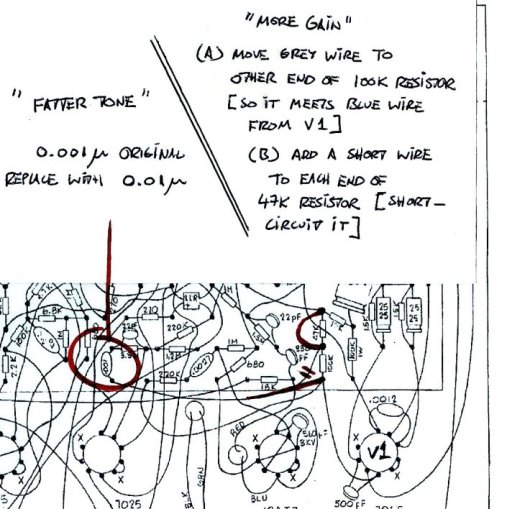
I hope this is clear enough - it shows the right-hand end (input end) of the circuit board with the valves/tubes nearest you.


Power Attenuator
I've made myself a variable speaker attenuator ( a very crude imitation of a Weber MASS, or THD Hotplate, or similar). This allows me to use the sound of the power valves running at maximum power, but with the final volume being as quiet as I want. WOO HOO! The folks who write about this are right  - it opens up a new world of tone. Just to be clear, this is an extra box which connects between the amp's speaker output jack and the speaker. It dumps actual power - it's not just a 'volume box' which some folks put in their amp's effects loop, which only works at line level. (In any case the PRII hasn't got an effects loop...)

With a PRII and a speaker attenuator, there are 2 basic options.
(1) With the amp set for 'clean' (so you're not selecting the 'lead' sound). I have the volume (input gain) set at 9 or 10. Then turn the attenuator down to low volume and turn the amp master up to 8, 9 or 10. This gives an on-the-edge blues sound. Add mid-boost for even more ZZ Top feel.

(2) For a more high-gain, squealing harmonics blues-rock sound, select 'lead' . Turn the lead level up to 10, turn the attenuator to low volume, and use the volume control to adjust how much preamp gain/distortion you want. Even if you don't like the 'lead' sound, you'll probably like this because it has the 'buzz' removed, and warmth added, by the 6V6s running at near-max power.

Obviously all this will change in character with a different set of 6V6s and/or with a change to the bias setup.

If you only ever run the amp on '3' the power valves will probably last forever. A power attenuator allows you to wear out the power valves faster, because you can play at max power all day without hurting your ears; with the master or the lead level on '10' the amp is working to the max whether it sounds loud or not!  This makes a clip-on fan a really good idea. It won't save the power valves but it will stop the valves and transformers heating up the rest of the amp so much.
--------------------
LOOSER,
MORE ORGANIC SOUND; MORE POWER AMP DISTORTION;
NEGATIVE FEEDBACK LOOP SWITCH
For
info about Negative Feedback Loops and
what they do, see
here. (no point in my trying to
re-write this kind of thing!)
I
have done this mod and only got a subtle change.
However another PRII owner says it makes for a big
difference. Maybe it's something to
do with my power valves being biased cool.
Referring to the schematic, there's a 100k resistor
at the top of the diagram, shown above v5 and v6,
forming a loop back
from the power transformer to the inputs of
v4. If that loop is broken (just unsolder one end of
that resistor) then the amp's power stage becomes
less hi-fi, looser, more organic, with power amp
distortion (i.e., nice distortion) appearing earlier
when the volume is increased. This is a very subtle effect
at low volume and only makes a real difference when
the volume is increased to rehearsal or gig level.
Advantages - slightly more maximum
volume, earlier onset of power amp distortion, more
touch-sensitive, warmer, less clinical sound.
Disadvantages - maximum clean volume is
reduced, slight increase in operating noise, slight
loss of extreme top and bottom end.
Side-Effect - the presence control won't
work. On my amp I can't hear any loss of presence,
possibly because I've added a little top end by cutting
out the snubber caps.
Risks - there is a theoretical
risk that an amplifier becomes unstable (makes a
hooting noise with no instrument connected) when a
designed-in negative feedback loop is removed. This
wasn't a problem on my amp and I don't think it
would be on any PRII.
IN PRACTICE - SIMPLE EXPERIMENT
Identify the 100K resistor and unsolder one end.
(Find the speaker socket - there are three wires
coming off it. One wire runs to the circuit board,
to the relevant 100K resistor). Play the amp,
keeping in mind the effect doesn't really kick in at
low volume. If you like the sound and the amp isn't
too noisy, consider leaving it like that. If not,
re-solder the resistor. (Never touch a live, open
amplifier while holding a connected guitar.)
WHAT I DID - MAKE IT SWITCHABLE - fully reversible mod
In summary, what I did was to park the 'hum balance'
control inside the amp and use the hole to mount a
small switch on the back panel. Two wires run from
the switch to the circuit board where the resistor
is. I'm writing this up after 4 months of using the
amp in various settings and I'm happy with the
effect and the reliability, and as stated above, the
loss of the presence control when switching to
modified operation doesn't seem to lose anything
tone-wise.
I don't know anyone who has ever needed to adjust
the 'hum balance' so I put it inside the chassis and
used the hole for the switch. This means there are
no changes to the chassis. Note the hum balance control
must be grounded to the chassis, otherwise
the amp makes a bad noise.
Parts needed - about 600mm of insulated
single-conductor wire, pretty much any kind so long
as it's insulated
- a switch, sub-miniature, latching, 2-position,
single-pole or double-pole, single-throw
-
I
used
a
50-60mm
strip
of
the
steel
strip
they
use
to
help mount car stereos. 2 of the holes had to be
drilled out a little.
This strip
re-mounts the hum balance control and grounds it.
You might think of a better way.
after removing
the chassis from the cabinet...
Step 1
solder about 300mm of wire to each of 2 tags on the
switch (make sure it's 2 tags which get connected in
one of the 2 switch positions)
2
unscrew the hum balance control, slide it into the
chassis.
3
screw the hum balance control onto one end of the
steel strip.
That's the hum balance control on the left.
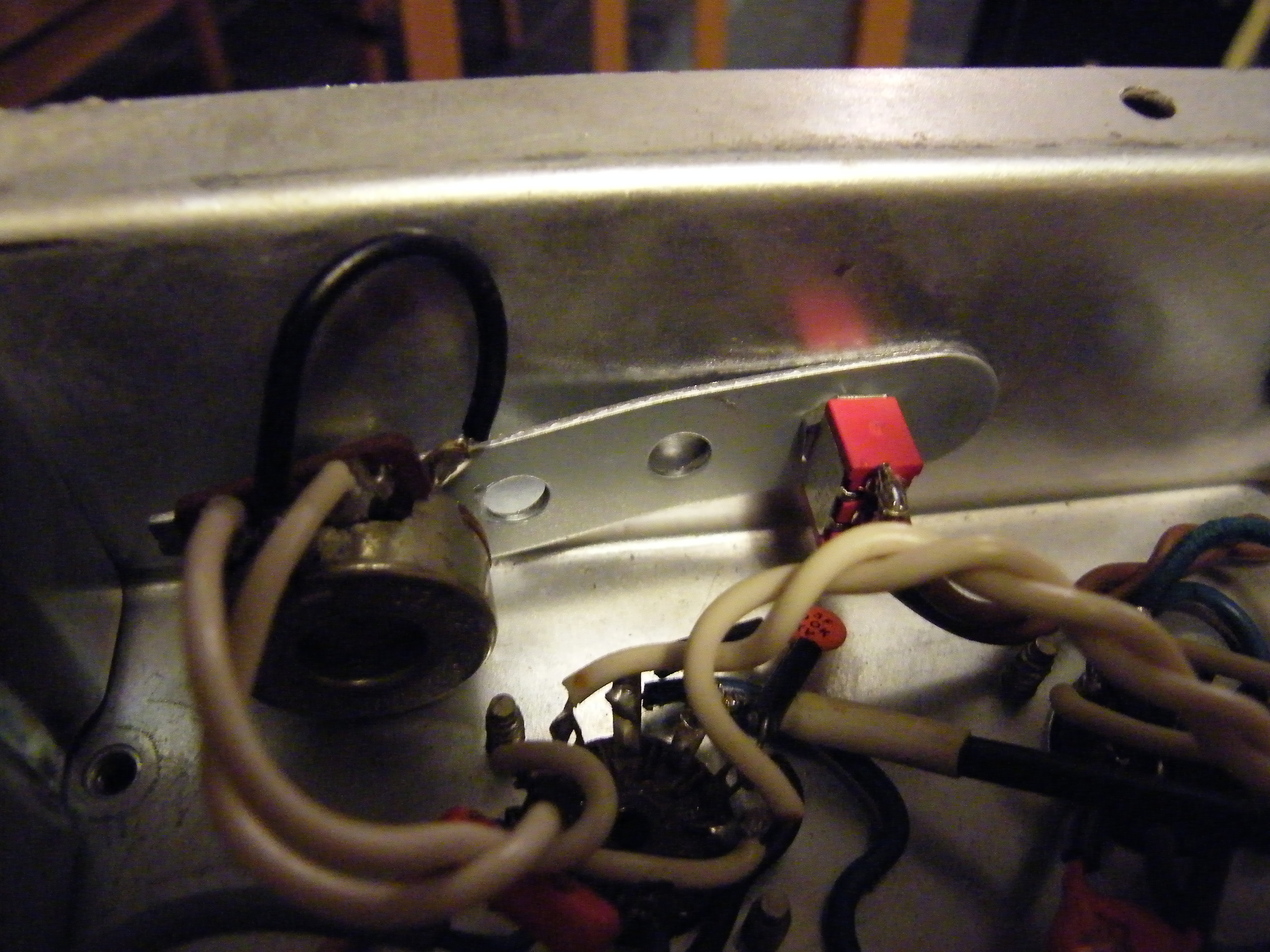
4
Use the switch to mount the strip and the hum
balance control to the chassis. In the picture
above the switch body is red. The hum balance
control is pushed against the inside of the
chassis (not sticking through it, there's no hole
there). The strip is under tension. The new wires
are brown and head away to the right of the photo
above.
5
feed the new wires toward the 100k resistor
(described above) which has one end lifted. I ran
the new wires under all the existing wires - they
hold it firmly against the bottom of the chassis
(see brown wires in the photo below). It's all
about keeping things neat and vibration-proof.
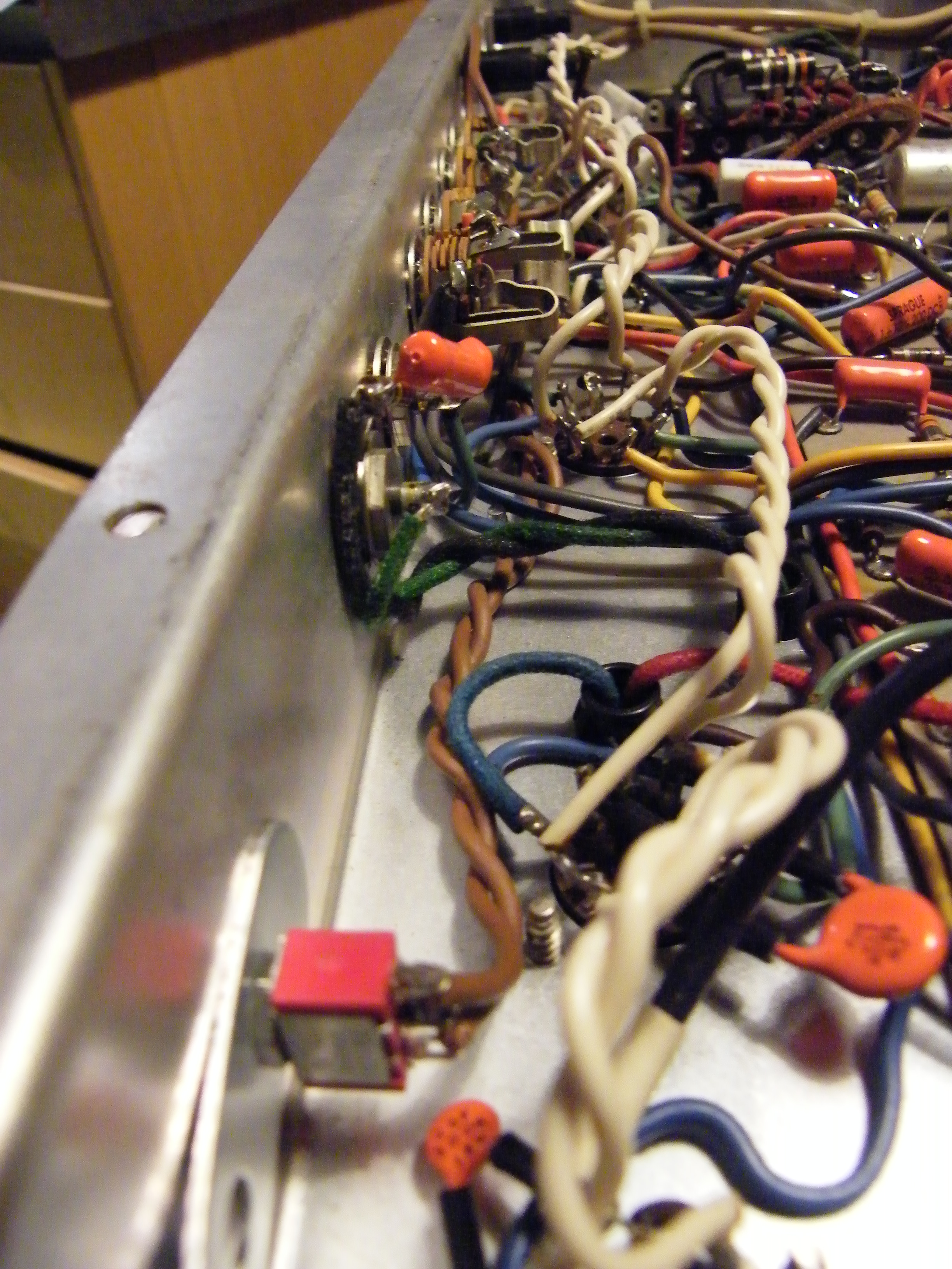
6
solder one wire to the lifted end of the resistor,
and the other wire to the circuit board where the
free resistor-end came from (see photo below).
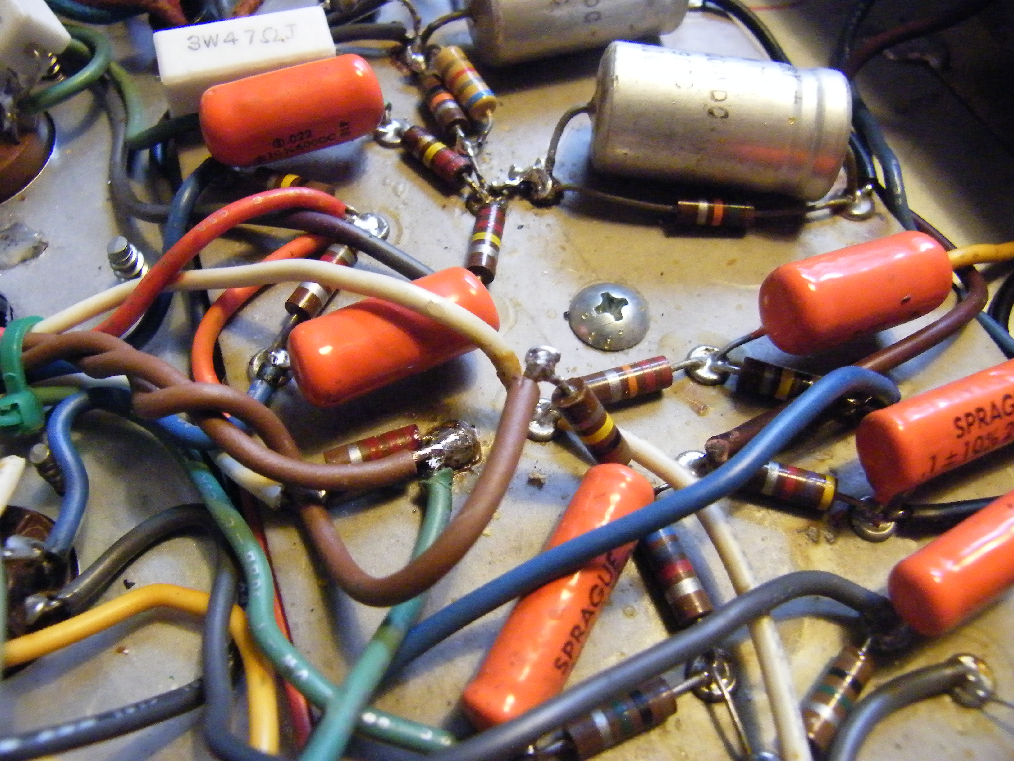
The
new
wires
arrive
from
the
left.
In
this
photo
the
valve
sockets
are
to the left. I used a green cable-tie (just visible
on the left) to tie the new pair of wires with some
existing wires. Because I used thick wire, the
raised resistor is rigid and I'm happy to leave it
like this.
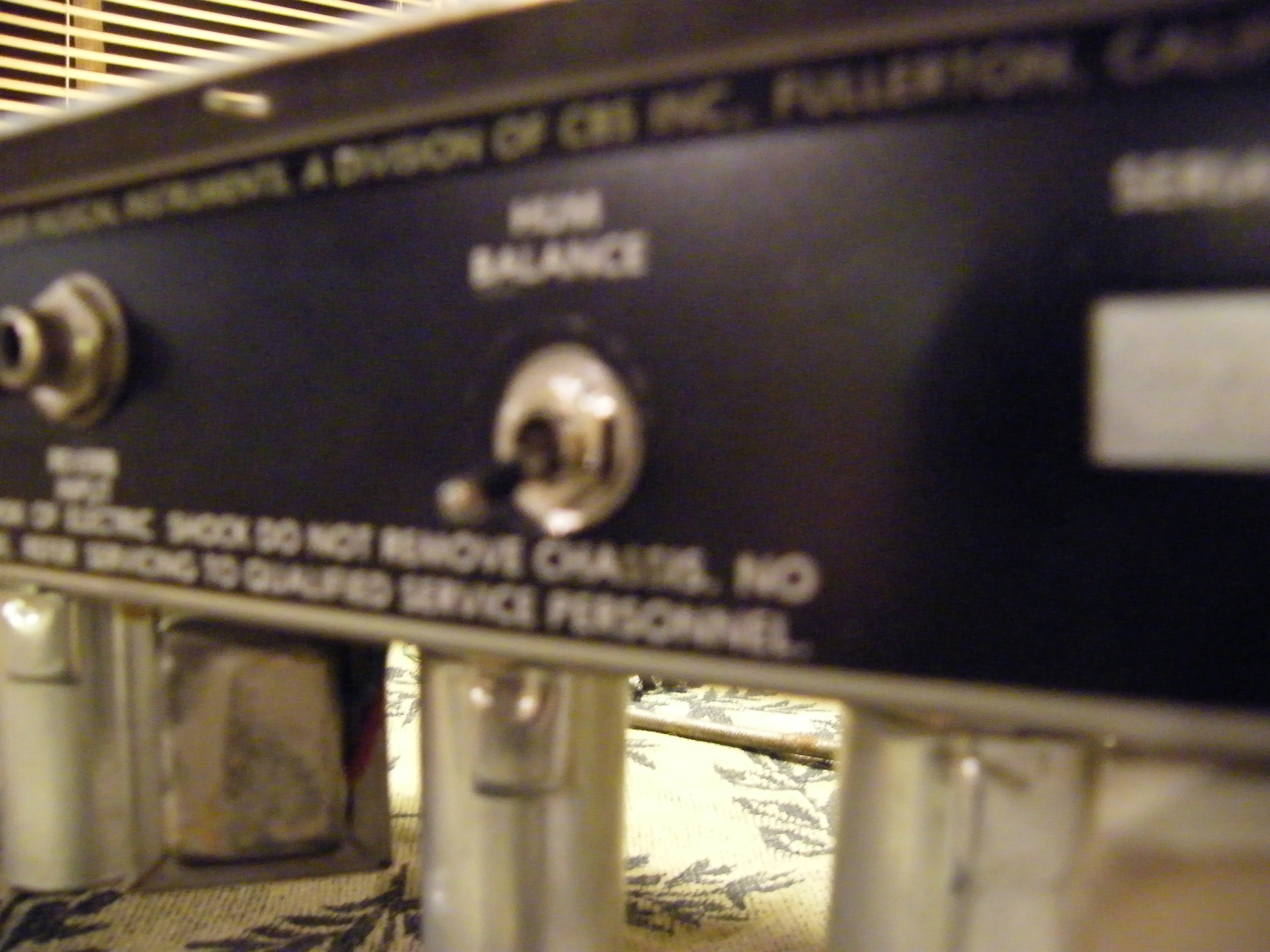
Here's
the
switch
viewed
from
the
outside
(sorry
it's
out
of
focus).
On
mine,
'down'
is normal operation and 'up' is modified, i.e. with
the Negative Feedback Loop disconnected. I've
since labelled them 'stun' and 'kill'.
back to top
home
rebiasing
dismantling