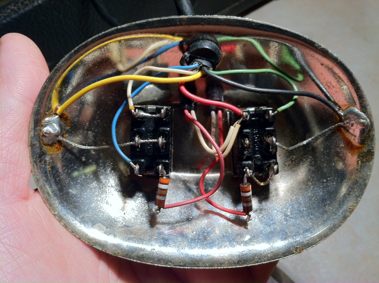
See the photo below - that's all it is folks; 2 buttons, ('lead'
and 'reverb'), 2 LEDs and a couple of resistors.... What's all
the fuss? You read a lot of stuff about the Rivera-era Fender
footswitch, some of it contradictory. Despite the
complexities inside the amps and the confusing
side-effects of using one, it is not a
complicated device and the mythology is nonsense.
Honest.
photo courtesy Harry Brill of Tiger Audio, Inc
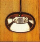
the 2 LEDs (one red and white wire each) are just under
the cable-entry at the top.
I'm grateful to several other
folks, especially contributors to the Fender Discussion
Page, for much of what I've learned so far.
If you've already got a
footswitch and you find it helps in practice, be happy. The 1983
catalogue lists it as 'optional', which means not all the original
owners bothered to buy one. Nearly All the Rivera-era Fender amps,
including the Princeton Reverb II (Princeton Reverb 2), used the
same footswitch. It's a simple design but very unusual - no other
series of amps has used it. If you've found a 2-button footswitch
and you're wondering if it will work with your PRII, have a look
at the other end of the cable. If it breaks out into two
stereo 1/4" jack plugs, one of them marked as 'red' in some way,
you may have the right one. If not, don't even try it; though it
might work with a bit of re-wiring - if it has 2 switches and 2
LEDs, 75% of the work has been done for you.
The Fender part no. was
017007. No other numbers, and sometimes not even this one, appear
on the Fender original (thanks for this info, CJ and Donk).
Amps using this footswitch
Princeton Reverb II*
Super Champ * (see Super Champ
page for amp schematics and much more)
Concert (112, 210, 410, and Top (Top = separate amp head)) **
Twin Reverb II **
Deluxe Reverb II **
Fender 75
(Note, Oct 07; Fender 75 users assure me this
footswitch works with the 75.)
Fender 140
(Jan 2012; looks fairly certain to me after looking
at the 140's schematic)
March 2012 - I am indebted to Bill Smith, who tells
me his Fender 30 f/s
has one stereo 1/4" jack
and one RCA (phono) connector. Therefore the Fender 30 uses a
different switching system
and is not compatible
with the the f/s described here. the
footswitch schematic for the Fender 30;
don't say I'm not good to you
* single-channel amp; 'red' button
selects lead (overdrive) effect
** 2 - channel amp; 'red' button switches
channels requirements for front panel settings or
pull-switches vary from one model to another - check
your amp's manual thanks to PartsSmart,
Dale Beachwood, Unquiet and others for confirming these
compatibilities schematics
for
these
amps
(not
the
footswitch)
including
Fender 75 and 140
Do I Really Need One?
This applies to PRII only; other amps, compatible
with this switch, may operate differently
...an open question! I've got to say, once I'd built one, I only
used it for a couple of numbers in my soul covers band,
where I want to turn reverb on and off at either end of a solo.
The 'lead' sound isn't that great and I never touch the other
button. (The 'lead' sound is preamp distortion. I love the
sound of this amp where 'lead' is NOT selected but the power stage
starts to overdrive.) In addition the amp doesn't offer
independent control of the tones for clean and lead sounds, and
the amount of distortion isn't independently adjustable. I use a
separate distortion effect box, a Marshall Guv'nor, but everyone's
got their favourite. This is all subjective. My point is, you
might want to think twice before going to any trouble to get a
PRII footswitch. See also Does it change the
amp's sound? below.
My son Sam, who played in a
punk/thrash band, pointed out another option worth considering; the
Human Footswitch. They once played at a festival where
the promised backline (shared with other bands) wasn't very good
and featured an amp with the wrong footswitch. Channel switching
was needed by the guitarist, so they got a friend to stand by the
amp and operate the front panel "channel" switch when the
guitarist nodded at him. It's cheap, it's organic, it promotes
friendship, it makes someone else feel involved, no special parts
or soldering required.... everyone's a winner. In fact, the young
man involved even found "I'm with the band; I'm the Human
Footswitch" to be a successful chat-up line. Young people
nowadays.
How To Use the Original Design,
2-button Footswitch
This applies to PRII and Super Champ for sure;
other amps, compatible with this switch, may operate differently
Plug it into the rear of the amp - there are 2 jack sockets
labelled 'red' and 'plain' and your footswitch jack plugs should
be similarly identified. Pull out the volume knob (as in "pull for
lead".) When you turn on the amp, one or both of the footswitch
LEDs may or may not come on initially but will alternate between
on and off as you work the switches. One switch will turn lead
sound on and off; the other will turn reverb on and off. The depth
of these effects still depends on knob settings.
The manual
(download size about 2MB) advises us to fit some cable
clamps to the inside of the cabinet to act as extra
strain-relief on the jack plugs. It makes the advice sound as
though the footswitch was intended to be permanently connected and
be stored inside the cabinet. I guess some kind of clip to stop it
rattling around would be in order....
Where to buy a Footswitch ready-made
... if you're sure you really want one...
In the US, Voodooman made one
for a time, but there were, lets say, issues.... Google it....
But you're good-to-go with the
following;
US Chuck at Superior Music in Mt Juliet, TN, USA....
sells new reproduction Fender footswitches, used original, & New old stock Rivera Fender footswitches. This outfit also devote a lot of webspace to one of the best list of musician jokes I've ever seen.
In Europe, the ever-helpful Tube Amp Doctor sell a reproduction of the original - see here
Rivera also used to sell a
footswitch for these amps. Makes sense, as Paul Rivera spearheaded
the design of this amp range for Fender. If you find a
Rivera-branded f/s with 2 stereo jacks and the 017007 part number
(which was the Fender number too) then it's probably fine for this
range of amps.
Other outlets are
(apparently - I haven't checked) Antique Electronics Supply, Mojo
Tone, New Sensor, Magic Parts, and Hoffman. Let me know if you've
tried any of these.
If you know another source,
please let me know.
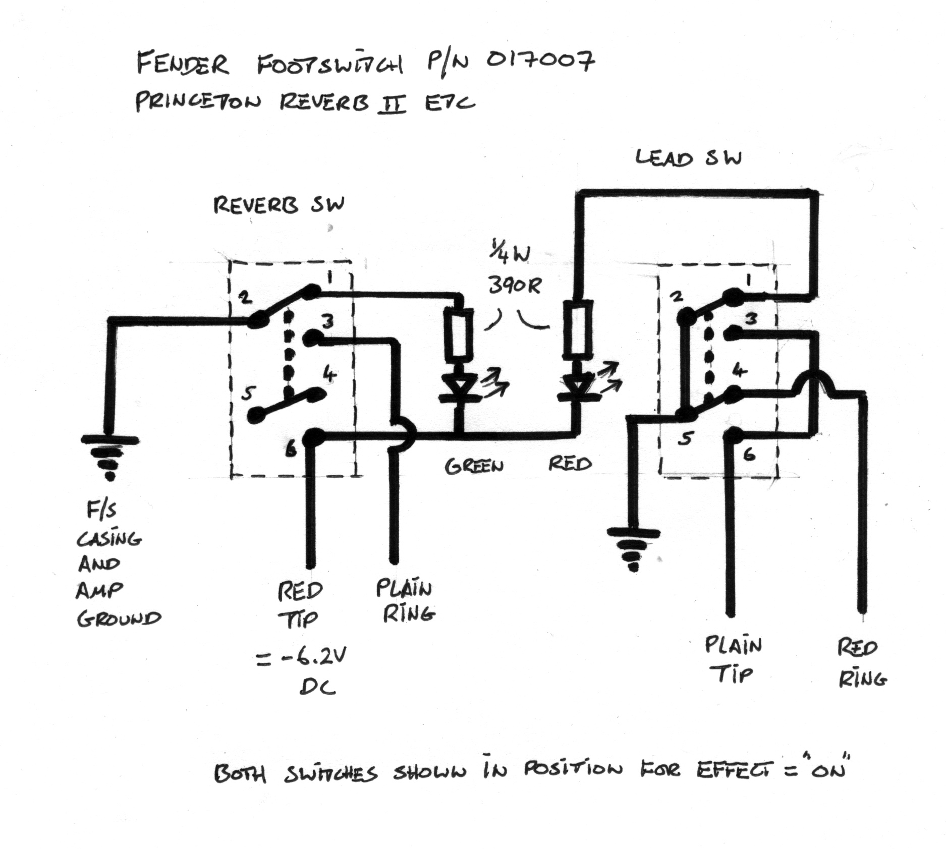
Original Design Schematic/Wiring
Diagram
The Fenderholic link doesn't seem to work any more so I drew my
own... the small numbers (1-6) on the switch tags coincide with
the instructions on "how to build one" below.
Does it Change the Sound of the Amp?
This applies to PRII only; other amps,
compatible with this switch, may operate differently.
Aug 08; I am told the Concert clean channel sounds weaker
when the footswitch is used. However, the
following paragraphs refer only to the PRII.
Because the footswitch is
rare, and thought by some to be complicated inside (it isn't, see
the photo at the top of this page), a minor mythology has
developed about it. Let me try to set the record straight. (1) Some believe there is a magical overdrive circuit or
tonal circuit which is only accessible via the footswitch. This is
not so. However... (2) With the footswitch connected, both the lead sound and
the clean sound will change. Some say they like the
change, some say they don't.
This is because, with the
footswitch connected, the 'lead' effect is switched in and out by
an optocoupler wired from signal path to ground. This contrasts
with footswitchless operation, in which the volume-knob-pull
switch opens or closes the 'lead' signal path (no grounding
action). Plugging in the footswitch introduces a resistance from
the signal path down to ground, which is switched from high to low
by the footswitch; so the sound has to be a little different. For
a much more detailed explanation see Here
comes The Science; how the effect switching works
On theSuper Champ page
you can see an official Fender drawing for this footswitch. My
drawing above is based on a hand-drawn sketch, faxed to my
amp's original owner by a Fender engineer. The two drawings are
basically the same. One Super Champ user built a f/s to my
drawing, got the 'loss in clean volume' problem described below,
spent another 100USD on an original Fender f/s and still
got the same problem. My page has been on the web since 2002 and
I'm still open to corrections. But if you build a f/s according to
these instructions and get the side-effects described on this
page, that's normal; it's not a fault with the f/s.
I've had some helpful email
traffic from three PRII owners (using footswitches from various
sources, not this page), all of whom say the clean sound is
significantly quieter with the footswitch connected. This
may not be desirable, but strictly speaking it's not a fault and
is explained 2 paragraphs up from here. You can hear this
effect without getting a footswitch - it might help you
decide whether you want a footswitch or not. You need two stereo
1/4" (6.35mm) jack plugs. Get right-angled ones if you think you
might end up using these plugs to build a footswitch.
on one jack plug, short the tip tag to the ground tag.
switch off the amp
push the "grounded tip" jack plug into the footswitch plain
socket
push the other jack plug (no connections) into the red socket.
pull out the volume knob ("pull for lead").
switch on and play.
The amp now thinks it has a
footswitch connected with 'clean' sound selected. You may find
it's quieter or has a thinner tone than "clean, no footswitch".
Switch off again before removing the jack plugs. The
highest voltage on any of the tags is 6V DC so this shouldn't be
a risky operation, but if your amp or the building wiring has a
fault, there may be some unspecified danger, so don't touch
those naked jack plug terminals while the amp is switched on.
The "loss of clean volume with
footswitch" problem may
have a solution here at post #5... plus, can be partially
overcome by following the example of Andrew W in Canada, who
says he gets his favourite sound like so; footswitch connected,
volume knob pushed in, lead LED on. On his PRII , with this
setting, (quote) "the gain of the clean channel increases
significantly like a kind of boost. It definitely creates a
kind of output overdrive effect, not to mention the lower mid
range spikes significantly making the tone very full and 'chubby'
sounding." I think this is something to do with the 0.003
uF capacitor wired across the lead level pot acting as an
alternative signal path with a bit of frequency-dependent
phase-shift . Andrew W is using the amp in a manner not
intended by the designer, but it's not harmful, and hey.... most
advances are made by misusing equipment, aren't they?. The
down side of working this way is, you can't get the amp's lead
sound with your foot. This doesn't matter to me, because
(as I said above) I don't like the amps' own lead sound, and I use
a separate stomp box for an overdrive sound.
I copied Canadian Andrew W for
the first six years I had a PRII; the footswitch is
connected, the volume knob is left pushed in, the lead LED is
always on, and the footswitch is only used for turning reverb on
and off. I didn't get his 'clean sound boosted'' phenomenon but
the clean sound was acceptable. Now (May 08) I use the reverb-only
footswitch.
There is another effect,
which I think is psychological. Assuming you're using the
footswitch as per the manual; if you have reverb on, and then also
turn lead on, the reverb almost vanishes. This is equally true
without a footswitch, but the footswitch allows you to compare the
sounds instantly, and so the death of the reverb seems more
marked. The reason why the reverb falls away like that is
explained on my page about what
the valves (tubes) do.
I'm always interested to hear
how yours behaves, especially if you've found a way to overcome
the 'drop in clean volume' problem.
Reverb-only
footswitch This applies to PRII only; other amps,
compatible with this switch, may operate differently
See here
for another way; a one-button footswitch for reverb only; avoids
the tone-sucking problem and could be best for you if you know
you're never going to need the 'lead' sound to be footswitchable.
How Do I Build the Original Design
Footswitch? Photos
of this project
Not difficult (the photos are intended to show it's pretty
uncomplicated in there). It took longer to do this write-up
than to build the footswitch. And the mechanical side of things
(ie building something which will survive gigs, cables jerking and
flexing etc) is more difficult than the actual electronics. On
eBay in the US, you occasionally see a firm selling new clones of
the original Fender chrome-dome type footswitch for this range of
amps. I imagine they're well-made and properly specified, and the
price looks reasonable. My only quibble is that they claim the
footswitch contains parts which are "not inexpensive" which I take
to mean "expensive"... if you've read that, don't let it put you
off. It isn't true. See the photo at the
top of this page - 2 switches, 2 resistors, 2 LEDs. Voila.
I hope techs and experienced
hobbyists will forgive me for spelling things out at a simple
level. When I start waffling about something which is blindingly
obvious to you, please jump to the next paragraph.....
You will need some very basic
soldering and metalworking skills, and...
parts list
- a suitable metal box; metal for strength and the necessary
electrical shielding.
- cable, 4-core plus screen (shield), you choose the length:
Fender's was 12 ft (3.6m). My cable is actually 2 screened twisted
pairs, which has no advantage electrically but makes wiring up 2
jack plugs much easier. 5-core without shield is no good; the
reverb signal actually travels up this cable and back down again,
and without the shield it will pick up noise.
- cable gland with strain relief
- 1 red LED
- 1 green LED
- 2 resistors, 390 ohm, 1/4 watt or 1/2 watt
- 2 switches, robust for stomping on, Double Pole Double Throw
(means there are 6 solder tags), latching action (= push on,
push off)
- 2 stereo jack plugs, with one marked red in some way. If you're
going to leave the footswitch plugged in all the time (ie even
when transporting the amp), you might want to use right-angled
plugs to stop them sticking out beyond the rear of the cabinet. I
wish I'd done that now.
- rubber feet for box
- solder, glue, paint(?)
The above bits cost me about
£11 (15 $US) in Oct 02, not counting the cable, which I had lying
around in the shed and knew would come in handy one day. I
love it when that happens.
Notes on the bits LEDs have a long lead and a short lead. Don't cut them
without some way of keeping track of which is which. On the
schematic above, the short leads are the ones nearest the bottom
of the page.
The 2 resistors are
identical and it doesn't matter which way around you solder them
into place. For connection clarity, I'm calling one (i) and the
other (ii).
Check your switches
with a continuity tester - you need to know which are the 2
'common' tags on each switch, and which are the tags sometimes
connected to 'common' and sometimes not. Almost certainly the
'commons' will be in the middle of the switch. I'm calling
the common tags 2 and 5. 2 alternately connects with 1 and 3 as
you repeatedly push the switch. Same for 4, 5 and 6....
Stereo jack plugs have
three separate conductors - the tip, the body
(goes to the screen/shield/braid) and the one in between, called
the ring. The back of the amp has 2 jack sockets for the
footswitch - one labelled 'red' and the other 'plain', so we need
to label the jack plugs accordingly...
I don't know what colours are
the cores in your cable. At the other end, they're going
to the stereo jack plugs. The screen goes to both jack plug
bodies. The four internal cores are going to 'plain' plug ring,
'plain' plug tip, 'red' plug ring, and 'red' plug tip. So I'm
labelling the four cores as below. I suggest you print this out
and write your cable colours against my labels.
my
label
your colour
cable plain ring .......................
cable plain tip ........................
cable red ring ........................
cable red tip. .........................
Assembly; (a) in the box
Lay out the switches and LEDs in a way that makes sense to you.
Decide where the cable entry should go. Drill out the box (5 or 6
holes = 2 switches plus 2 LEDs plus one cable entry, plus
another hole if needed to screw the braid/shield/screen to the
box). File the hole edges free of fine debris and don't leave any
in the box.
My switches came with a couple
of metal washers. I soldered a short piece of wire to one of the
washers and used that as my box (shielding) connection. Photos
of this project
Fit switches and LEDs.
The Fender original, right way up, in use, with the cable-entry
away from you, has lead switch (and red LED) on the right. I use
red-for-lead, but I put that on the LEFT in order to match what
I'm used to from a previous amp. You choose your own layout and
make your own adjustments if it's different to mine.
I drill holes for the LEDs
which are a snug push-fit, push the LED through from inside to
outside, and blob some epoxy glue (Araldite) on the inside to hold
it in place. It's worth roughing up the metal area where the glue
touches, to give it more 'key'. Separate the cable cores, turn the
braid into a 'tail' which can be attached to the box, and push it
all through the gland and into the box. Make sure the cable is
held firmly by the gland (it's not the job of the solder
connections to take the strain when someone trips over your
footswitch cable).
Solder the connections as
shown in the schematic above, or as detailed below as fifteen
connections.
LEDs don't like being heated
up, so don't solder too close to the LED body or for too long.
Length of all connections is a trade-off between too short
(connections under strain) and too long (flapping around and
working loose).
Reverb switch; (on
right when my box is in use, so on left while working inside the
box!)
1 tag 1 to resistor (i)
2 resistor (i) other end
to green LED long lead
3 green LED short lead
to tag 6
4 tag 6 to red LED short
lead
5 tag 2 to box
6 tag 3 to cable Plain
Ring
7 tag 6 to cable Red Tip
(note, tags
4 and 5 on reverb switch are unused)
Lead switch;
8 tag 1 to resistor (ii)
9 resistor (ii) other end to red LED
long lead
10 tag 2 to tag 5
11 tag 5 to box
12 tag 3 to tag 6
13 tag 3 to cable Plain Tip
14 tag 4 to cable Red Ring
15 Shield/braid/screen
of outgoing cable to box.
Assembly; (b) other end of
the cable
Now you need to solder the stereo jacks. They both should end up
with the cable shield soldered to the 'body' tags, and the other 4
cores soldered to rings and tips as per your colour code chosen
above. How you break out one cable to two jacks is up to you, but
you need to make them robust and jerk-proof. Both kinds of jerk,
in fact.
As I said earlier, my cable
was easy to break out to 2 jacks because it's 2 screened twisted
pairs. Both screens are attached to the box. The 'y' junction at
the jacks end is reinforced with gaffer tape (duct tape). Not
pretty but it works.
Another option is;
- cut the outer insulation back by about 200 mm (8 inches)
- push one jack plug body onto the cable (I forget this at least
once in any project involving connectors)
- clamp the whole cable in the strain-relief of one jack plug
- wire up that plug normally (ie cut the 2 cores, intended for
that plug, to a sensible length and solder into place) BUT leave
the other 2 cores long and don't cut the 200 mm braid; solder it
in place leaving most of it free
- push the 200mm of the 2 remaining cores plus screen back out of
the jack plug (this may necessitate widening the hole on the jack
plug body with a drill)
- push the other jack plug body onto these long cores and screen
- wire up the second jack plug
Another option might be to use
heatshrink sleeving to protect a 'Y' junction of cable, where it
splits off to go to 2 jack plugs. I think some places sell
specially-shaped bits of sleeving for this purpose.
Continuity Test
Just to make sure, I checked the following continuities at the
jack plugs before using the footswitch...
Plain Jack
body - box; connected permanently
tip - body; connects and disconnects as you work the lead switch
ring-body; connects and disconnects as you work the reverb switch
Red Jack
body - box; connected permanently
tip - body; no connection
ring-body; connects and disconnects as you work the lead switch
The above
advice is offered in good faith but I accept no responsibility
for loss, damage, injury, death, destruction, pestilence, chaos
etc etc. All the construction info above is in the public
domain, but it's based on designs owned by Fender, and I'd
appreciate it if you'd treat my write-up and photos as copyright
2002 Andrew Waugh. Thanks.