NEW! possible solution to the 'clean tone
suck' problem Oct 2017
email me... stratopastor (at) hotmail (dot) com
updated Dec 2013; better understanding of why
the clean sound is weak when the footswitch is
used
This page gets down to component level in order to
explain (or try to) how the less obvious parts of the circuitry
work.
As with this entire site, this info (or these theories)
are offered in good faith but I can't take responsibility for
the death or your amp if you make any changes as a result of
reading this. There are lethal voltages inside valve/tube amps
even when they are switched off.
All the descriptions on this page refer to the PRII
schematic
Why the Clean Channel goes quiet with the Footswitch connected
Why you get some clean boost with f/s but
with the knob pushed in
How the Effect Switching Works; Reverb
Without
Footswitch
V2 drives the reverb transformer, which wiggles the reverb
springs. The motion of the springs is picked up and amplified by
half of V3, which passes this pure reverb signal to the reverb
control. That sends the chosen amount of pure reverb via 1.2Mohm
resistor into the main signal path at the input to V3b.
With Footswitch
Same as above, except the pure reverb signal is also sent all the
way out to the footswitch. "F/s reverb off" switches the pure
reverb signal direct to ground (actually the f/s casing) - a zero
resistance compared with the high (1.2M) resistance it would
have to overcome in order to get into the main signal path; so you
don't hear any reverb. "F/s reverb on" opens the f/s reverb
switch, so the ground path isn't there and the pure reverb signal
behaves as though the f/s wasn't there at all, ie, it heads for
the main signal path through the 1.2M resistor. In this setting
the f/s also allows the -6.2V supply, through an LED and a 390ohm
resistor, to go down to ground (all inside the f/s), so you get an
LED indication that reverb is on.
How the Effect Switching Works; Lead
The overdriven, distorted sound is made by taking a huge, boosted signal from V2 via the input (primary) side of the reverb transformer and sending it to the main signal path at V3b, thus distorting V3b and everything after it. But how does that big signal get there?
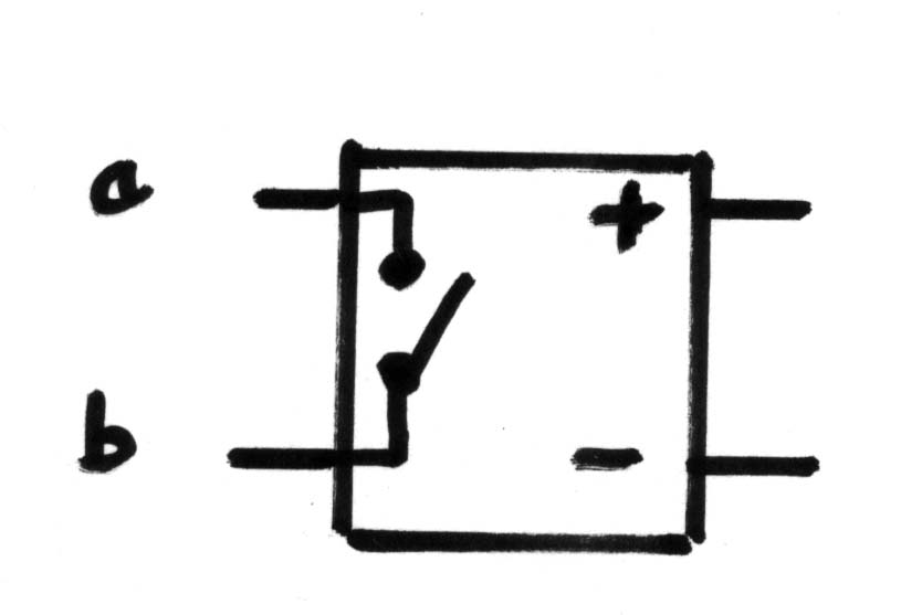
For this you have to
understand how the optocouplers work. There are 2 identical
optocouplers, each one shown on the schematic like this. I'll
label the 4 terminals a,b,+ and -.
Inside the optocoupler, a is
not connected to + or - at any time. Also b is not connected to +
or - at any time.
When there's a positive DC
voltage from + to - , a connects to b by a low resistance.
It's not quite a perfect zero resistance (like a good mechanical
switch) but it's close. Let's call this "on".
When + and/or - is
disconnected, the resistance from a to b goes very high. It's not
infinite (as in a good mechanical switch) but it's high enough to
be called "off".
In the PRII these optos are
connected with - permanently wired to -6.2V. That's 6.2V BELOW
ground level. So connecting + to ground will turn the opto
"on" because + will be 6.2V ABOVE - . (The -6.2V is also
used to power the LEDs in the footswitch; it comes from a 6.2V
zener which is connected to the bias supply circuit for the power
valves/tubes.)
I'm going to call the opto
drawn near V3a "OC1" and the other opto "OC2".
Without Footswitch
The 'pull for lead' knob closes 2 mechanical switches on the back
side of the volume knob. The schematic is drawn with these
switches 'on', that is, the volume knob is pulled out. One switch
is drawn near OC1 and when 'on' it allows the boosted signal to go
straight to the input of V3b via a 220K resistor. The other switch
is drawn near the red f/s socket. When 'on' it connects OC2's + to
ground, via the ring terminal of the red socket, turning OC2 on.
This connects the non-signal end of the lead level pot to ground
via OC2's a and b, thus allowing the pot to act like a pot -
so it becomes a volume control for the whole amp in conjunction
with the master volume.
When 'pull for lead' isn't
pulled (ie you want the clean sound), both switches are open. The
boosted signal never gets into the signal path. OC2 is off, so the
bottom end of the lead level pot goes nowhere - it just 'floats'.
Therefore it can't act as a volume control and its setting doesn't
matter.
Without the footswitch OC1 is
always off and so never affects the signal routing.
With Footswitch
For operation according to the manual, "Pull for lead" should
always be pulled when the f/s is connected, so both
pull-switches in that control are on. When the f/s red plug is
connected, this operates an extra switch in the red socket so that
the ring terminal isn't always grounded. This means OC2's + can
only be grounded via the f/s 'lead' switch.
With the f/s set for 'clean',
OC2's + isn't grounded, so OC2 is off and the lead level control
is out of circuit as described above. Meanwhile OC1 is turned on
by having its + grounded by the lead switch in the f/s. Therefore
the boosted signal goes down to ground via OC1's a and b. So you
don't hear the boosted signal and the lead level control has no
action.
With the f/s set for 'lead', OC2's + is grounded via the lead switch in the f/s, so the lead level control is in operation. OC1's + is disconnected from ground via the lead switch in the f/s, so OC1 is off and the boost signal heads up to V3b instead of down to ground. Also the lead switch in the f/s grounds another f/s LED, which is fed -6.2V via another 390ohm resistor, so you get an LED showing lead is on.
To summarise the footswitch
action (if you're following this on the schematic, remember the
pull-switches are 'on', which is the way the schematic is drawn,
and the grounding-switch built into the red socket is 'off'
because a jack plug is in place)
| MODE | PLAIN TIP |
OC1 |
RESULT |
RED RING |
OC2 |
RESULT |
| clean |
grounded |
on |
boosted signal grounded |
floating |
off |
lead level control not in circuit |
| lead |
floating |
off |
boosted signal gets through |
grounded |
on |
lead level control in circuit |
Why the Clean Channel goes quiet with the Footswitch connected
Problem
The clean sound is much louder and fuller without the footswitch.
When the footswitch is connected, the clean sound is quieter and
thinner.
Reason (1) my
original theory... but see below for reason 2, new Sep
2017
In clean mode without the f/s, the pull-switch is open (so no lead
sound gets into the signal path) and OC1 is off, so there's no
path to ground for either the clean or lead sound.
In clean mode WITH the f/s, the pull-switch is closed (allowing
lead sound to go further into the circuit) and OC1 is on, sending
the lead sound straight to ground so it still doesn't get into the
signal path. My theory is, if OC1's on-resistance is too high (in
a perfect world it would be zero) therefore not all of the 'lead'
signal is shorted to ground. Therefore, it arrives at the input to
V3b at low level (ie not enough to distort V3b, so the sound you
hear remains clean). The clean signal (the signal we want, ie the
signal that's come from the tone stack, not the reverb stage) also
arrives at this point. Here's the problem; because the reverb
driver inverts what is sent to it, the two signals are out of
phase, making the end-result weak. (The reverb driver
inverts that signal.)
Reason
(2) as offered by Ben on the TDPRI forum - more
convincing than my own idea!
See
post #5 on this page. I have not tried this yet but it makes
sense to me - if it works, you only need to add a 1M
resistor.
Why this problem is
bigger in some PRIIs than others
Several factors affect this problem;
Why you get some clean
boost with f/s but with the knob pushed in
This is the 'Andrew W of
Canada' operation mode described on the main footswitch page.
Connect the footswitch, select lead on the f/s, DON'T pull
the volume knob, and on some models you get a slightly fatter
clean sound. I have been pondering why this should be.
The two modes in question are
(a) knob in, f/s connected, lead selected on f/s
(b) knob in, f/s not connected
(a) is a little louder and has
a mid boost compared to (b) . Why?
I get the same effect with V2
removed. V2 is the source of the lead boost; therefore the boost
is nothing to do with the extra gain introduced by V2. What's left
which could make a difference?
If you compare what's going on
between these two modes...
(a) has OC1 off and OC2 on.
One f/s LED is on.
(b) has OC1 and OC2 both off. No LEDs are on.
I don't see what
possible effect this has on the -6.2V rail, and even if it did
vary a little I don't see what difference that would make.
The only thing that's left is
the action of OC2. In (a) mode, OC2 is on, grounding the
bottom end of the lead level pot and the 0.003 capacitor in
parallel with it. In (b) mode, the OC2 is off, allowing the bottom
end of the lead level pot to float and passing the signal to V4
through part of the lead level pot, and through the 0.003
capacitor which is in parallel with it.
I think the 0.003 cap is the
thing making the difference - it's either in the signal path
(mode b, normal clean no f/s) or it's a path to ground (mode
a, gives some mid boost). Is this a phasing thing - boosting
volume by grounding some frequencies which would otherwise reduce
volume by a phase-cancelling effect? I'd be grateful for any
comments on the logic (or otherwise) of this analysis