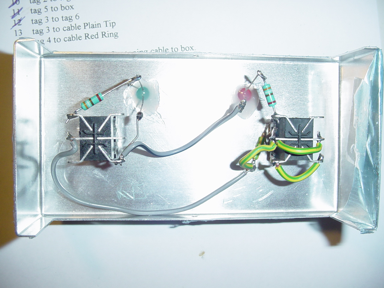
As you can see, the inside wiring really isn't very complicated. This view shows the switches with the tags same way up as in the switch diagram (not the f/s schematic), ie 1,2,3 down the left side and 4,5,6 down the right side. The left switch is reverb (which appears on the right when the f/s is in use). You can see the blobs of glue holding the LEDs in place. The LED long leads are near the top of the photo. The LEDs are placed so that, outside, they're protected from foot- and transit-damage by the switches, which stand taller. The right-hand switch has a short piece of yellow/green wire soldered to its washer, and that's acting as the box connection.
For clarity, I took this photo before adding the 5 cable connections. See below the photo for where they go.
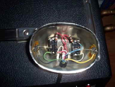
To tell you the truth I'm not that proud of my handiwork - as I look at it now, I can see a few things that would have made more sense in terms of internal layout. But hey, it's solid, it works, and I've felt better about it since seeing the inside of a Fender original (see bottom of this page!)
The 5
cable connections should go as follows - looking at the switches
as you see them in this photo -
Left (reverb) switch; left middle contact = "2" = f/s casing and amp
ground (shields). Left lower contact = "3" = plain ring. Right lower
contact = "6" = red tip.
Right (lead) switch; left lower contact ="3" = plain tip, also
connected as shown to right lower = "6". Right upper = "4" = red ring.
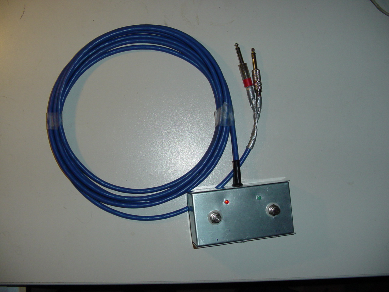
below).... Construction over..... the protective plastic film is still on the outside of the box. Maybe I'll peel that off and paint the box black. Maybe I'll label the switches. Maybe I'll get around to it eventually. (Note Feb 04; a few months after taking these photos I painted it black (2 coats of Hammerite) but I didn't bother to label the switches. Oh, and it worked fine through many gigs and rehearsals. It's now retired because I use a reverb-only footwitch these days, but it still works. )