Cap Job
parts needed
method
cap can replacement
email me.....
NOSPAMstratopastor@hotmail.com
home
This page describes how to
do the preventative maintenance work known as the 'cap job'
- replacing all the electrolytic capacitors in the Fender
Princeton Reverb II guitar amplifier. (No other model
of Princeton! Only the 'II'!)
Disclaimers;
(1) this page refers to no other type of amp. There may be some similarity to other Fender Rivera-era amps but I have never been inside them.
(2) SAFTEY RULES APPLY! Valve (tube) amps develop LETHAL VOLTAGES while running, and store them in charged components EVEN WHILE SWITCHED OFF AND DISCONNECTED FROM THE OUTLET / MAINS SUPPLY. These voltages are MUCH HIGHER than the outlet voltage, and higher than anything you'll find inside a transistorized amp. The cap job means working on the highest-voltage sections of the amp, If this scares you, good. Inside a chassis, don't use your fingers to touch anything which isn't insulated or earthed (grounded). Don't stick more than one hand in at a time, and keep the other hand well away. Use insulated fine-nose pliers to manipulate components. NEVER, ever, work inside a live amp while holding a connected guitar.
(3) Some skill and knowledge is required. This job involves dismantling, soldering, removing old components and adding new ones, and possibly some work with a hacksaw. The concepts are simple and the job is not complicated but (unlike most of the other mods and maintenance jobs I've done) if you get some things wrong in here, your amp could self-destruct. If you're not sure what you're doing, get local help. The details in this whole site are believed accurate but you act on them at your own risk. I have to disclaim any responsibility for injury, damage, loss of value or loss of gig due to inoperative equipment.
(4) sorry if this write-up goes into more detail than you need. I'm assuming some relatively inexperienced people will try this.
Why do this job?
Electrolytic capacitors have a limited life. They contain liquid chemicals and when they die, they might die in a small explosion which spreads nasty liquid chemicals around the inside of the amp. If they go short-circuit they'll probably blow one of the amp's fuses.
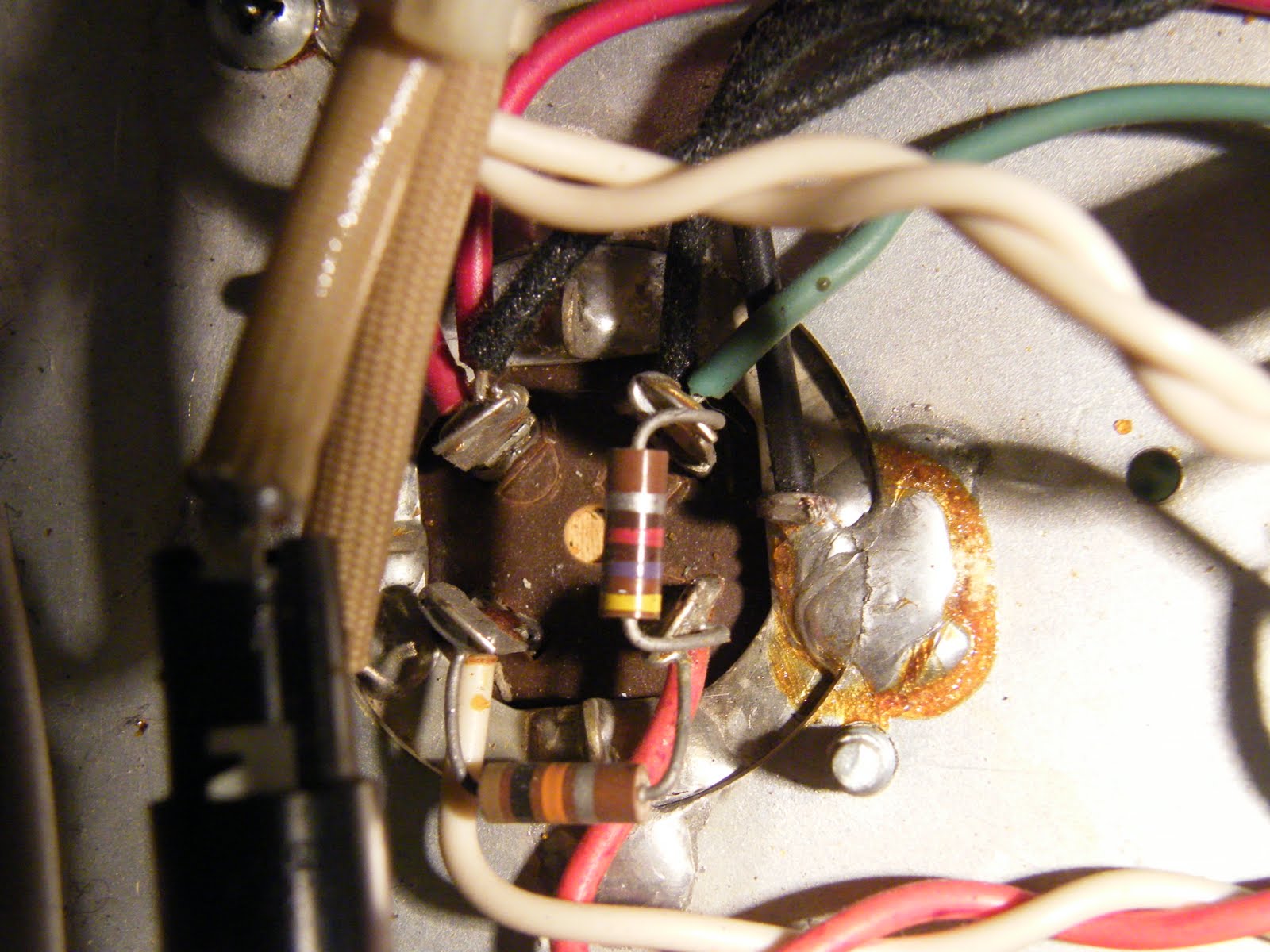
Here's an interior photo of a PRII which was blowing fuses. Can you spot the leaky cap?
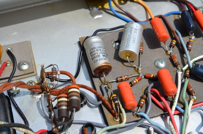
thanks to NoSoapRadio of the Fender Discussion Page
When?
Some say twenty years, some say thirty. The capacitors (caps) will last longer if the amp is used at least occasionally rather than stored unused. My PRII is from 1984 and I did this job in 2010. I have to say the amp's sound did not change at all, there was no sign of cap leakage, and it feels like I could have left it for longer (say another 5 years?). But hey ho, it's done now, and to be honest my goal is to be with Jesus by the time it needs doing again. I don't know how old the PRII in the above photo is, but it can't be more than 4 years different from mine because they were all made between 1982 to 1986; and in any case, at this range, issues of how-much-used and how-stored will have a bigger influence on when a cap job is due.
Parts
All the capacitances on this page are in microfarads. This is usually abbreviated uF, (or mF, which is wrong.. that would be millifarads.)
This job needs eight new parts;
The 25uF caps shape the tone of the amp and must be replaced with 25uF, though the 25V rating isn't crucial and can be higher. 25/25 caps are easy to find.
I could not find new 4uF and 70uF caps but these do not shape the tone - they only smooth the ripple out of sections of the amp's DC power supply. Therefore they can be replaced with caps of higher capacitance and voltage the same or higher. I used 10uF 500V and 100uF 100V. For these caps I'm sure any good brand will do, "Sprague Atom" and "F+T" being the most respected. I bought Sprague Atoms from Watford Valves here in the UK.
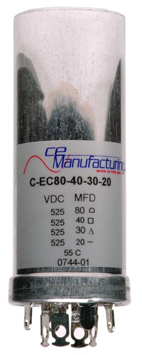
The cap can is made by CE and available from Antique Electronic Supply in the US for 42 US dollars (January 2016).
Greg B in Australia has kindly let me know that these instructions helped him do the same job on his Deluxe Reverb II, which makes sense as the power supply is identical to the PRII's power supply (NB the electrical design is identical - the physical layout, wiring colours etc, may be different). He found a second source for the cap can in Northern Germany - Frag Jan Zuerst - their site is in German, English and French (see flags in their top right-hand corner) - then you want catalogue / capacitors / 1.Authenticaps, and scroll down to the bottom of the Authenticaps page for their part number KTL25. They use F+T caps to assemble these (very respected German brand) and the price is 37 Euros (January 2016). Big thanks to Greg for finding this part and letting me know. Also, Tube Amp Doctor do the CE can for 54 Euro (Jan 2024). These guys also sell an insulating mounting. You don't want one of these insulators! You want a good electrical connection from the can to the chassis... Also you might want a new mounting plate, also from Tube Amp Doctor. (Thank for the link Andreas S !) More about that below.
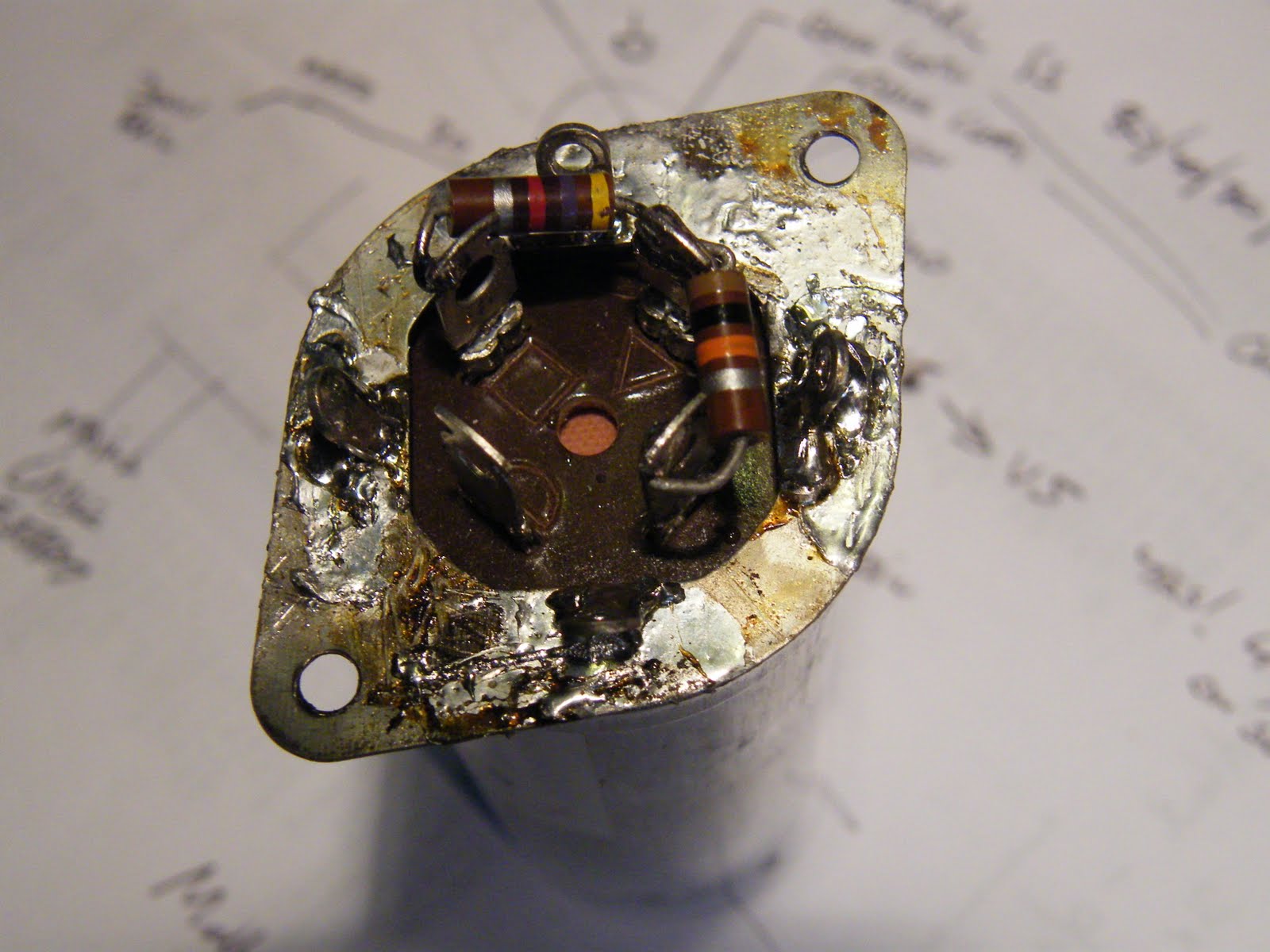
As you can see one of the caps inside is 30uF, not 20uF like the original, which is OK because it's a bigger value and these caps are only used for smoothing DC. Both models of cap can mentioned above are a direct electrical and mechanical replacement - the physical size, the location of the 4 electrical connections (5 if you count the body of the can, which is the negative terminal for all 4 of the caps inside) and even their identifier markings are the same as the original. (The Authenticap has a zero where the original and the CE has a blank.) At the bottom of this photo you can see the 4 electrical connections, which stick down furthest, and 2 of the 4 mounting legs, which are smaller and nearer to the edge of the can.
If you can't obtain a replacement cap can, then I imagine you could improvise with four separate caps. In this situation the biggest concerns would be finding room for the new caps inside the chassis and making them mechanically secure.
Tools
Screwdrivers for dismantling, soldering iron, solder, small wire cutters, sharp knife, vice, hacksaw, small metal file, voltmeter is useful but not vital.
Method
Dismantle the amp and supporting the chassis so you can work comfortably on the circuit board.
I used an extension speaker cable to keep the speaker connected so, after replacing each cap, I could check the amp still worked without moving it or reassembling. NB this can be risky - I made sure the guitar never came close to the amp and the amp was switched on/off by connecting/disconnecting an extension power outlet cable, so I could play the guitar without standing near the live, open amp. Also I always checked the voltage on one of the cap can tags was near-zero before continuing work.
Check, again, the amp is not connected to the mains outlet. On the circuit board, identify one of the 6 electrolytic caps. Note which way around it lies - there is a groove around the cap near one end, which marks its positive end. Unsolder the cap or cut it out, and solder in its replacement. Make sure it's the same way around as the original and lying flat and vibration-proof. Repeat for the other electrolytic caps.
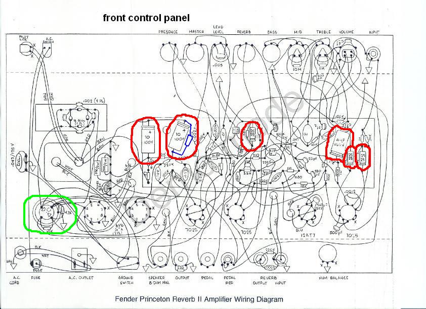
viewed like this, with the rear panel nearest you, the six electrolytic caps on the circuit board are - shown in red, left to right - 70uF, 70uF (note beside this cap the original Fender wiring diagram has a resistor missing - shown here in blue), 25uF, 4uF, 25uF, 25uF.
Replacing the cap can (shown in green above) takes most of the time for this entire job.
Make your own drawing of all the wiring on the can's 4 tags. Don't just take photos - they aren't always as clear as a drawing. Here are my notes but check the wire colours for your amp...
Unsolder all the wires.
Gently unsolder and remove the two resistors - keep the 10k for re-use; if it looks damaged then new ones cost very little. Throw away the 4K7; its wattage is about 30% too low, which is why you're replacing it with 4k7 1W. I am grateful to Dirk Buffel in Belgium for pointing this out to me in 2022. Dirk is a hobbyist vintage amp restorer. I waited until the next time I opened the amp to replace this resistor. The old resistor's value about 30% high, the resistor didn't look overheated and the voltages in the amp were OK, but if you're doing everything else on this page I would still suggest you replace this resistor.
Turn the chassis over and unscrew the 2 screws for the cap can.
Gently rock the cap can from side to side to break the solder joint to the chassis, and lift the cap can away. Do not throw it away yet.
The CE cap can (Also the Tube Amp Doctor) does not come with the "ears" for the 2 screws, which are on a separate mounting plate. This must be removed from the old cap can - or you can buy a new one from TAD - big thanks to Andreas S for the link. Here is my mounting plate, which I cleaned up and re-used.
Disclaimers;
(1) this page refers to no other type of amp. There may be some similarity to other Fender Rivera-era amps but I have never been inside them.
(2) SAFTEY RULES APPLY! Valve (tube) amps develop LETHAL VOLTAGES while running, and store them in charged components EVEN WHILE SWITCHED OFF AND DISCONNECTED FROM THE OUTLET / MAINS SUPPLY. These voltages are MUCH HIGHER than the outlet voltage, and higher than anything you'll find inside a transistorized amp. The cap job means working on the highest-voltage sections of the amp, If this scares you, good. Inside a chassis, don't use your fingers to touch anything which isn't insulated or earthed (grounded). Don't stick more than one hand in at a time, and keep the other hand well away. Use insulated fine-nose pliers to manipulate components. NEVER, ever, work inside a live amp while holding a connected guitar.
(3) Some skill and knowledge is required. This job involves dismantling, soldering, removing old components and adding new ones, and possibly some work with a hacksaw. The concepts are simple and the job is not complicated but (unlike most of the other mods and maintenance jobs I've done) if you get some things wrong in here, your amp could self-destruct. If you're not sure what you're doing, get local help. The details in this whole site are believed accurate but you act on them at your own risk. I have to disclaim any responsibility for injury, damage, loss of value or loss of gig due to inoperative equipment.
(4) sorry if this write-up goes into more detail than you need. I'm assuming some relatively inexperienced people will try this.
Why do this job?
Electrolytic capacitors have a limited life. They contain liquid chemicals and when they die, they might die in a small explosion which spreads nasty liquid chemicals around the inside of the amp. If they go short-circuit they'll probably blow one of the amp's fuses.
Here's an interior photo of a PRII which was blowing fuses. Can you spot the leaky cap?
thanks to NoSoapRadio of the Fender Discussion Page
When?
Some say twenty years, some say thirty. The capacitors (caps) will last longer if the amp is used at least occasionally rather than stored unused. My PRII is from 1984 and I did this job in 2010. I have to say the amp's sound did not change at all, there was no sign of cap leakage, and it feels like I could have left it for longer (say another 5 years?). But hey ho, it's done now, and to be honest my goal is to be with Jesus by the time it needs doing again. I don't know how old the PRII in the above photo is, but it can't be more than 4 years different from mine because they were all made between 1982 to 1986; and in any case, at this range, issues of how-much-used and how-stored will have a bigger influence on when a cap job is due.
Parts
All the capacitances on this page are in microfarads. This is usually abbreviated uF, (or mF, which is wrong.. that would be millifarads.)
This job needs eight new parts;
- electrolytic capacitor, 25uF, 25V, quantity 3
- electrolytic capacitor, 4uF, 450V, quantity 1
- electrolytic capacitor, 70uF, 100V, quantity 2
- multi-stage electrolytic capacitor, 80 / 40 / 20 / 20uF, 450V, quantity 1 (see below; this is the "cap can", the aluminium tube which stands outside the chassis beside the 6V6GT power tubes)
- resistor, 4700 ohms 1W,
quantity 1 (this item new May
2022; the original resistor should be
replaced as its wattage is too low)
The 25uF caps shape the tone of the amp and must be replaced with 25uF, though the 25V rating isn't crucial and can be higher. 25/25 caps are easy to find.
I could not find new 4uF and 70uF caps but these do not shape the tone - they only smooth the ripple out of sections of the amp's DC power supply. Therefore they can be replaced with caps of higher capacitance and voltage the same or higher. I used 10uF 500V and 100uF 100V. For these caps I'm sure any good brand will do, "Sprague Atom" and "F+T" being the most respected. I bought Sprague Atoms from Watford Valves here in the UK.
The cap can is made by CE and available from Antique Electronic Supply in the US for 42 US dollars (January 2016).
Greg B in Australia has kindly let me know that these instructions helped him do the same job on his Deluxe Reverb II, which makes sense as the power supply is identical to the PRII's power supply (NB the electrical design is identical - the physical layout, wiring colours etc, may be different). He found a second source for the cap can in Northern Germany - Frag Jan Zuerst - their site is in German, English and French (see flags in their top right-hand corner) - then you want catalogue / capacitors / 1.Authenticaps, and scroll down to the bottom of the Authenticaps page for their part number KTL25. They use F+T caps to assemble these (very respected German brand) and the price is 37 Euros (January 2016). Big thanks to Greg for finding this part and letting me know. Also, Tube Amp Doctor do the CE can for 54 Euro (Jan 2024). These guys also sell an insulating mounting. You don't want one of these insulators! You want a good electrical connection from the can to the chassis... Also you might want a new mounting plate, also from Tube Amp Doctor. (Thank for the link Andreas S !) More about that below.
As you can see one of the caps inside is 30uF, not 20uF like the original, which is OK because it's a bigger value and these caps are only used for smoothing DC. Both models of cap can mentioned above are a direct electrical and mechanical replacement - the physical size, the location of the 4 electrical connections (5 if you count the body of the can, which is the negative terminal for all 4 of the caps inside) and even their identifier markings are the same as the original. (The Authenticap has a zero where the original and the CE has a blank.) At the bottom of this photo you can see the 4 electrical connections, which stick down furthest, and 2 of the 4 mounting legs, which are smaller and nearer to the edge of the can.
If you can't obtain a replacement cap can, then I imagine you could improvise with four separate caps. In this situation the biggest concerns would be finding room for the new caps inside the chassis and making them mechanically secure.
Tools
Screwdrivers for dismantling, soldering iron, solder, small wire cutters, sharp knife, vice, hacksaw, small metal file, voltmeter is useful but not vital.
Method
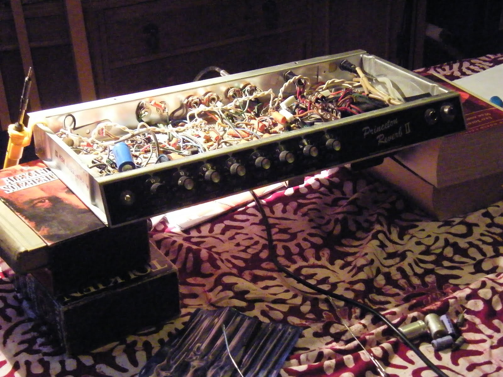
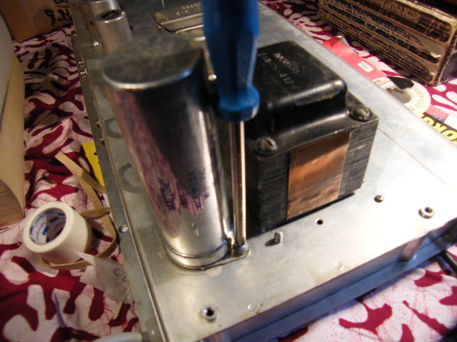
Dismantle the amp and supporting the chassis so you can work comfortably on the circuit board.
I
recommend Solzhenitsyn, Tolkein, Doestovesky and
Tolstoy for supporting the amp. And that is, of
course, our best tablecloth.
I used an extension speaker cable to keep the speaker connected so, after replacing each cap, I could check the amp still worked without moving it or reassembling. NB this can be risky - I made sure the guitar never came close to the amp and the amp was switched on/off by connecting/disconnecting an extension power outlet cable, so I could play the guitar without standing near the live, open amp. Also I always checked the voltage on one of the cap can tags was near-zero before continuing work.
Check, again, the amp is not connected to the mains outlet. On the circuit board, identify one of the 6 electrolytic caps. Note which way around it lies - there is a groove around the cap near one end, which marks its positive end. Unsolder the cap or cut it out, and solder in its replacement. Make sure it's the same way around as the original and lying flat and vibration-proof. Repeat for the other electrolytic caps.
viewed like this, with the rear panel nearest you, the six electrolytic caps on the circuit board are - shown in red, left to right - 70uF, 70uF (note beside this cap the original Fender wiring diagram has a resistor missing - shown here in blue), 25uF, 4uF, 25uF, 25uF.
Replacing the cap can (shown in green above) takes most of the time for this entire job.
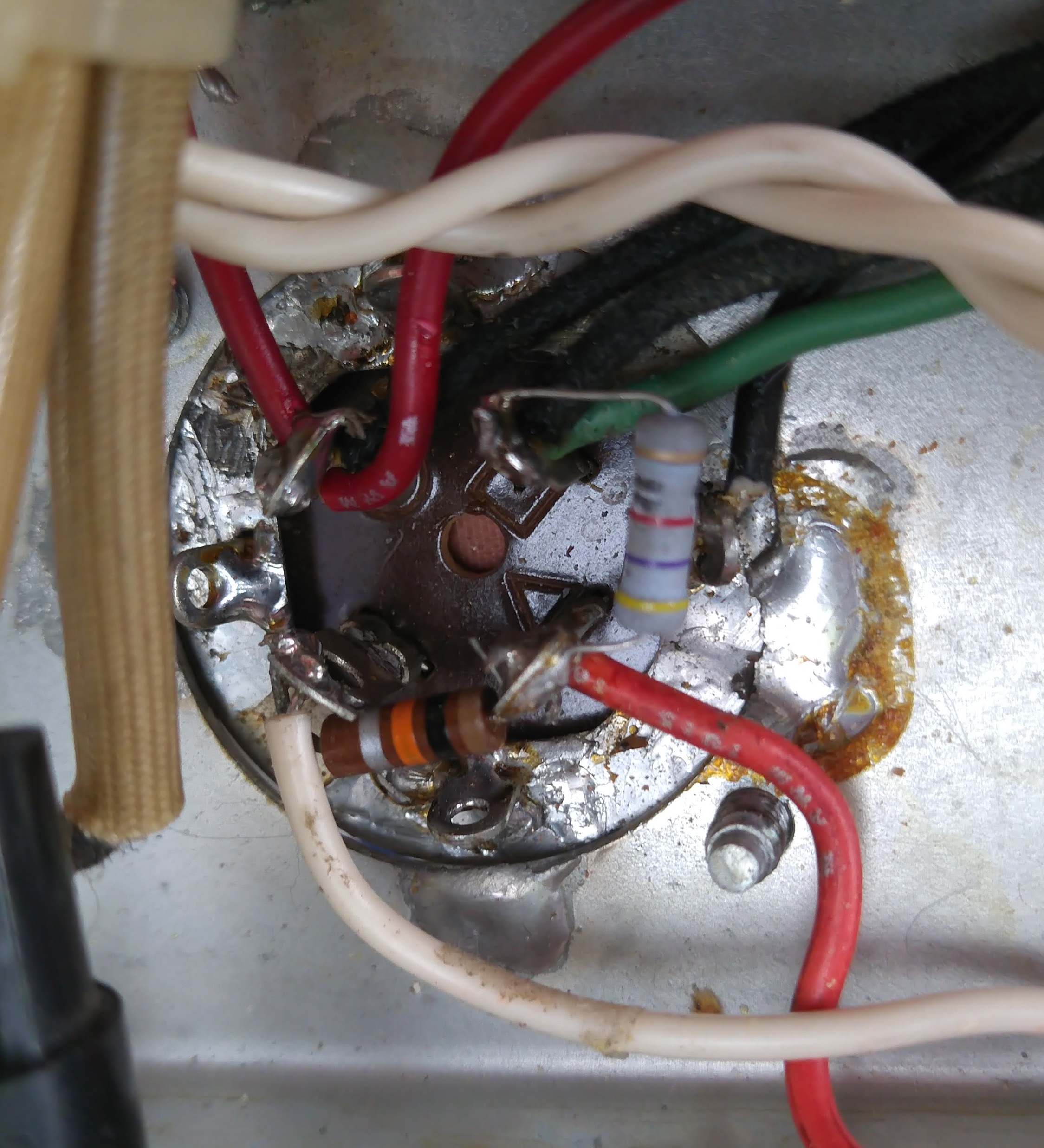
Make your own drawing of all the wiring on the can's 4 tags. Don't just take photos - they aren't always as clear as a drawing. Here are my notes but check the wire colours for your amp...
- half-circle tag - 80uF - black wire to choke, red wire to rectifier (small circuit board), red wire to output transformer centre tap
- square tag - 40uF - black wire to choke, green wire to power tube
- 4k7 resistor from square to
triangle tag - you are going to replace this if
you haven't already done the three reliability
mods (new May 2022)
- triangle tag - 20uF - red wire
to circuit board (this is 30uF on the new can; makes
no difference in practice)
- 10k resistor from triangle tag to unmarked tag
- unmarked tag on CE version = tag marked '0' on Authenticap version - 20uF - white wire to circuit board
- body of cap can - black wire
to rectifier board and solder joint direct to
chassis
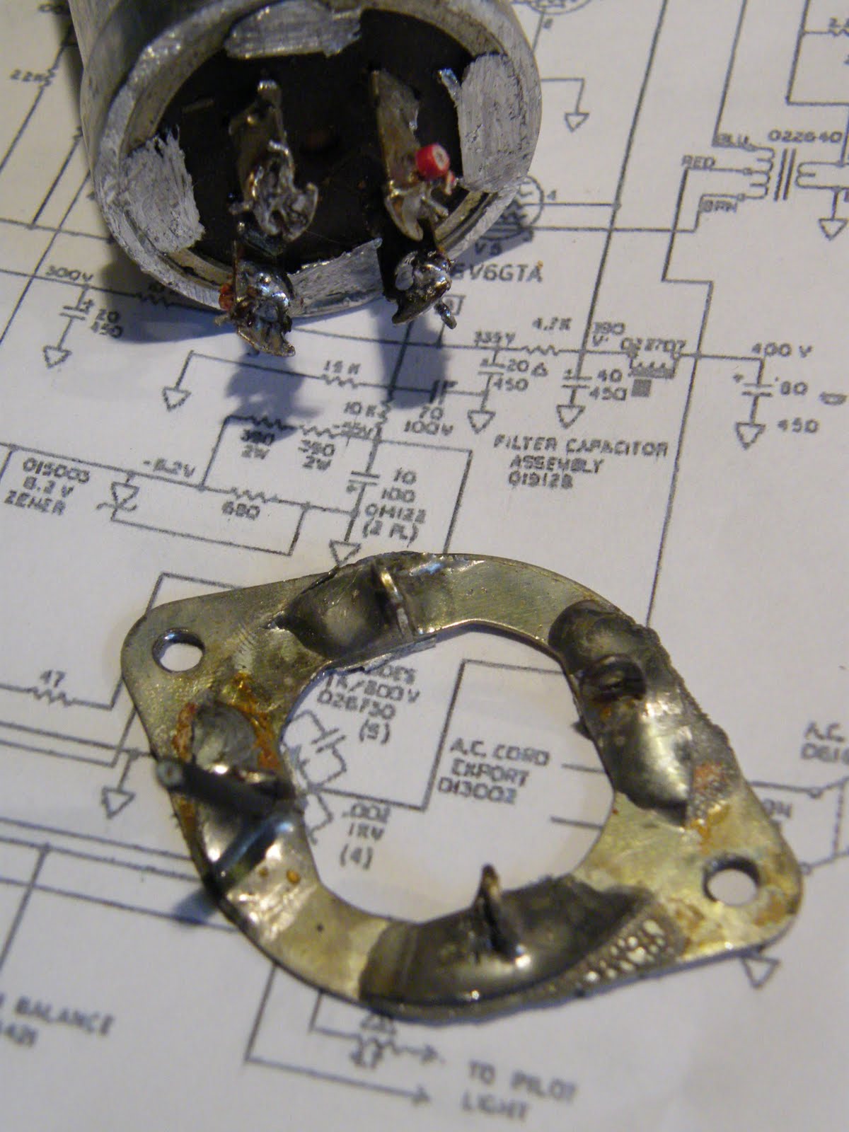
original
wiring,
same
view
as wiring diagram - note half-circle marker beside
the top left-hand tag, and the large solder joint
from the cap can to the amp's chassis (actually the
joint is cracked)
Unsolder all the wires.
Gently unsolder and remove the two resistors - keep the 10k for re-use; if it looks damaged then new ones cost very little. Throw away the 4K7; its wattage is about 30% too low, which is why you're replacing it with 4k7 1W. I am grateful to Dirk Buffel in Belgium for pointing this out to me in 2022. Dirk is a hobbyist vintage amp restorer. I waited until the next time I opened the amp to replace this resistor. The old resistor's value about 30% high, the resistor didn't look overheated and the voltages in the amp were OK, but if you're doing everything else on this page I would still suggest you replace this resistor.
Turn the chassis over and unscrew the 2 screws for the cap can.
Gently rock the cap can from side to side to break the solder joint to the chassis, and lift the cap can away. Do not throw it away yet.
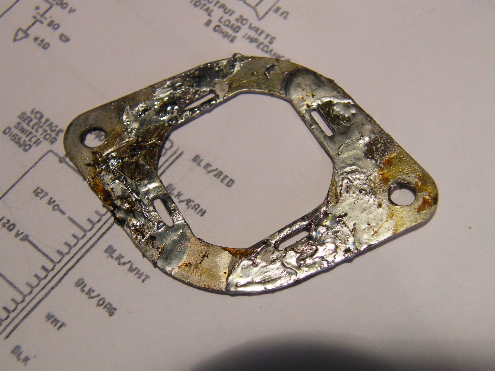
The CE cap can (Also the Tube Amp Doctor) does not come with the "ears" for the 2 screws, which are on a separate mounting plate. This must be removed from the old cap can - or you can buy a new one from TAD - big thanks to Andreas S for the link. Here is my mounting plate, which I cleaned up and re-used.
It is held onto the old cap can with 4
soldered "legs" - they fit through the 4 oval slots in
the photo above.
I put the cap can in a vice and sawed through the legs to release the mounting plate. A soldering iron and a very small file are needed to remove the old legs and clear the holes. Use a larger file to make the mounting plate as flat as possible on both sides - otherwise the new cap can will not stand up straight.
Alternatively you can buy a new mounting plate from (big thanks to Andreas Stoll in Swabia for this)
(have a look at the next step and consider there may be a better way to do it. I soldered the mounting plate to the new cap can and then mounted the whole thing on the amp. But if you've got a powerful enough soldering iron to re-make the solder connection from the mounting plate to the chassis then maybe it would be better to screw the mounting plate to the chassis, THEN re-make the solder connection to the chassis, THEN fix the cap can into the mounting plate. That way, you're not heating up the cap can when you make the solder joint to the chassis.)
Push the mounting plate onto the 4 legs of the new cap can. Make sure it goes all the way on all 4 legs (again, reasons of straightness). Bend each leg a little and solder each one. Fit the 2 resistors as before. Here is my new one....
the square
and triangle markers are visible in this photo
You might find it easier to
replace the resistors (original 10K and new 4k7) before
putting the can back in the amp.
Screw the new can into position (the same way around as the old one, not 180 degrees different).
Resolder all wires as before, with the original 10K resistor and your new uprated 4k7 if you didn't add them earlier.
If you have a powerful enough soldering iron, remake the solder connection from the mounting plate to the chassis. I didn't, trusting the screws to make a good enough ground-connection, and this has worked out OK. If the amp develops some new 'hum' in the future, this may be the reason.
... and that's all, apart from testing and reassembling. My amp made a small amount of extra hum for a few minutes and then went back to quiet operation. I assume this was one or more of the new caps "re-forming". I did this job one year after I bought the parts - unused caps sometimes need a voltage applied to them for a few seconds in order for them to work at their full capacity.
Here's a photo of the cap can in position with the 4k7 resistor replaced (the new one is grey). The amp's rear panel is at the bottom of the photo.
Now go and practice the guitar.
If you have any suggestions as to how to do this job easier or better, then please email me.
All of the technical information on this page is either in the public domain or copyright Fender. I would be grateful if you would regard this writeup and these photos copyright Andrew Waugh 2010.