Fender
Montreux*, London Reverb and solid-state Showman** amps;
footswitches
Fender
(1980s) part number 021702 (4-button) and 021703
(3-button)
This page launched Sep 2013
Feb
2014, correction to connector pin labelling
*often spelled Montreaux
in 1980s Fender documents!
** Not the earlier tube amps of that name; this is strictly about the 1983-84 transistorised Showman
back
to Fender Rivera-era solid-state page
email me at SPAMOFFstratopastor@hotmail.com (remove the capital
letters)
Dec 2016 - original Fender 4-button
footswitches for sale here
in the US!
Todd runs a music store in Colorado. You'll be dealing with
him direct and I take no responsibility.
I bought a London
Reverb in June 2013. Questions about the footswitch seems to
come up on the internet now and then, so I hope this helps.
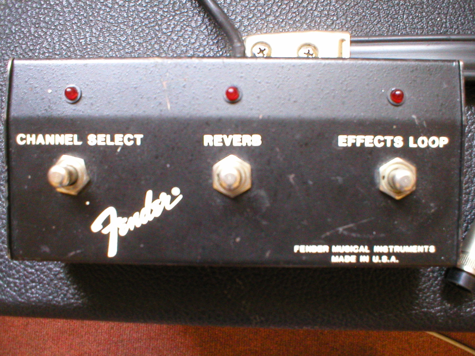
above - Montreux footswitch.
Fender part number 021702. Works these 3 functions for the other 2
amps too.
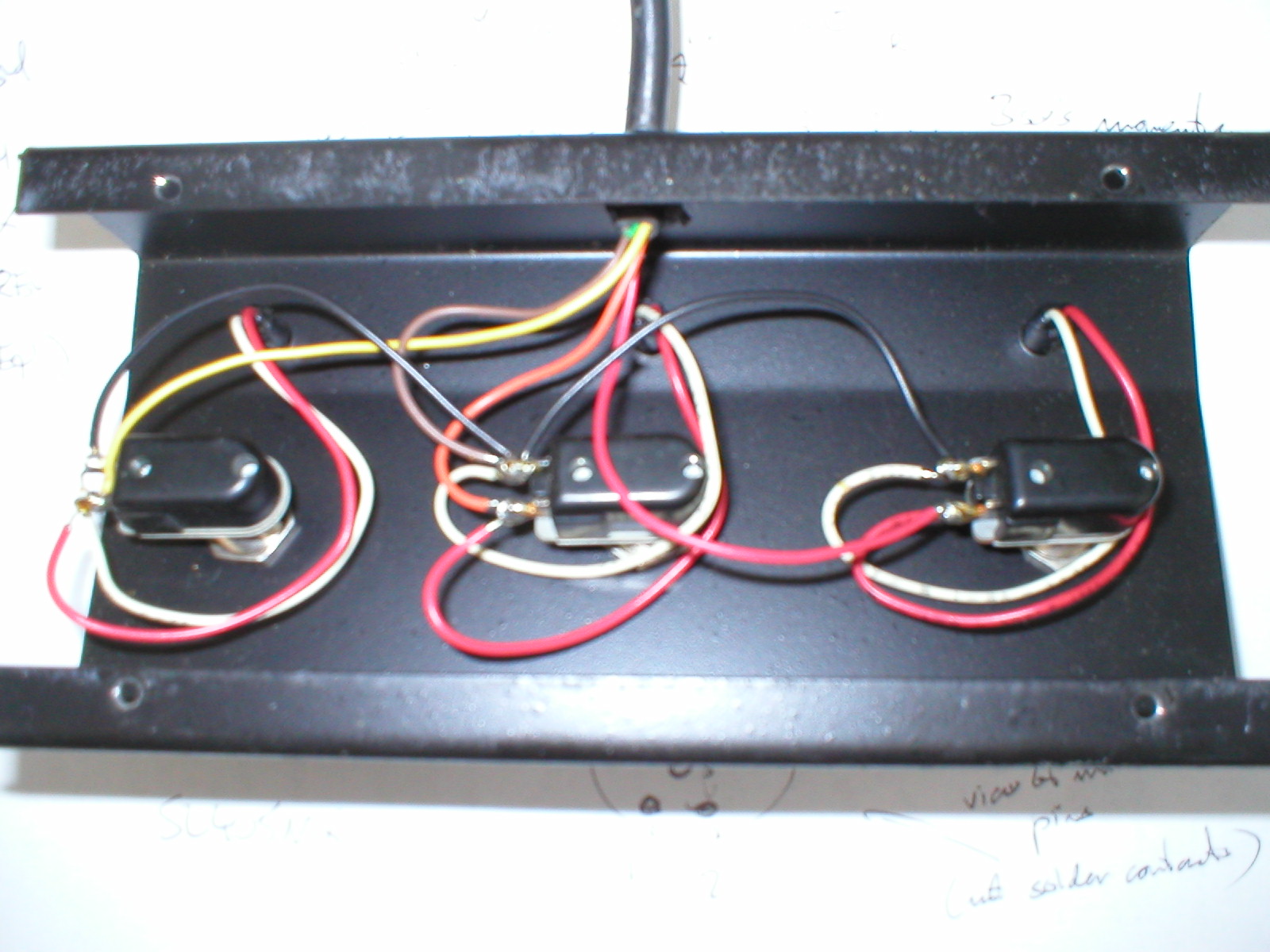
The wiring colours in the right-hand photo aren't clear but they
are (left to right) yellow (effects), orange (reverb), channel
(red). The brown wire in the middle is common ground.
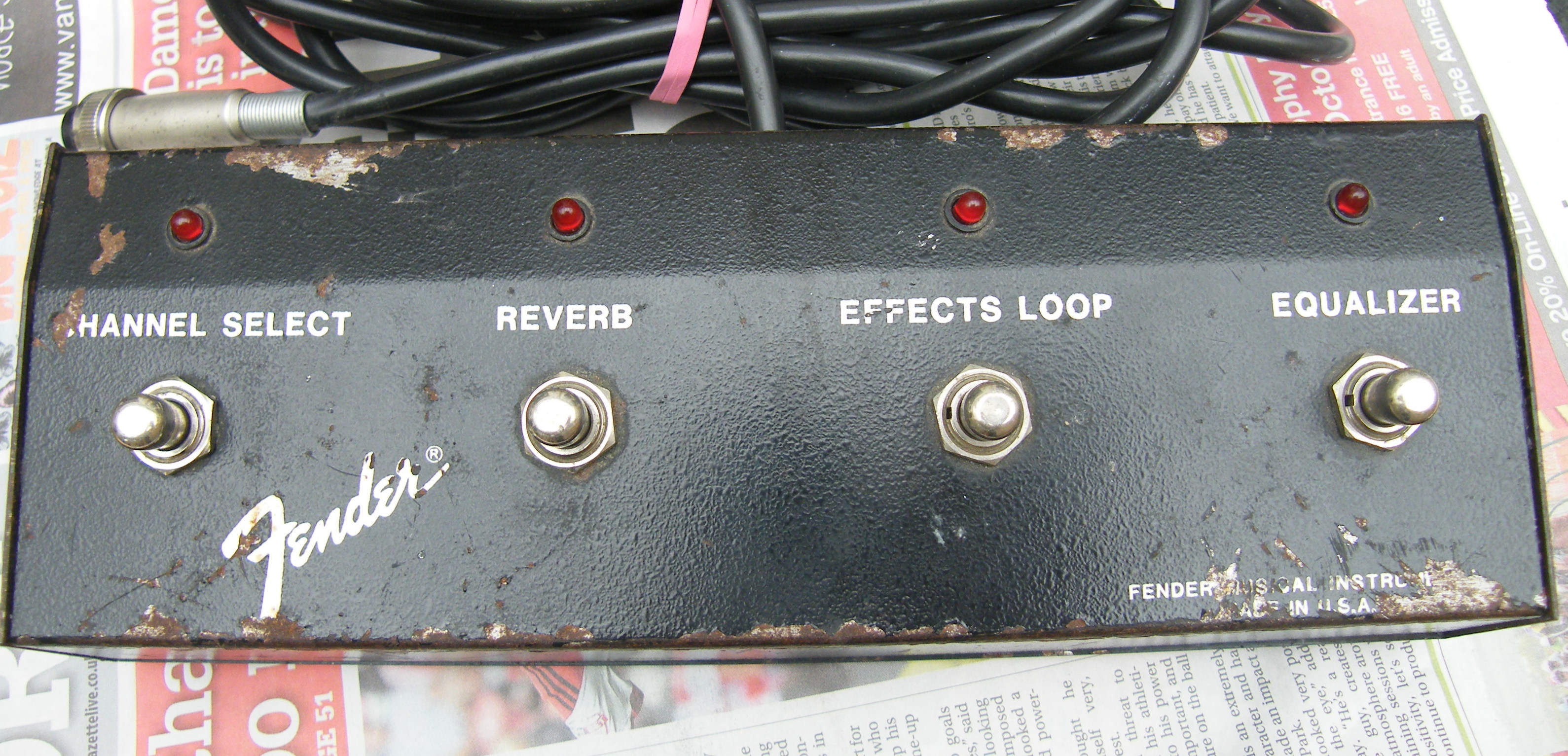
above - footswitch for London
Reverb and Showman. Fender part number 021703 Works for the
Montreux too.
(sorry about the paintwork; it's not the years.... it's the
mileage.)
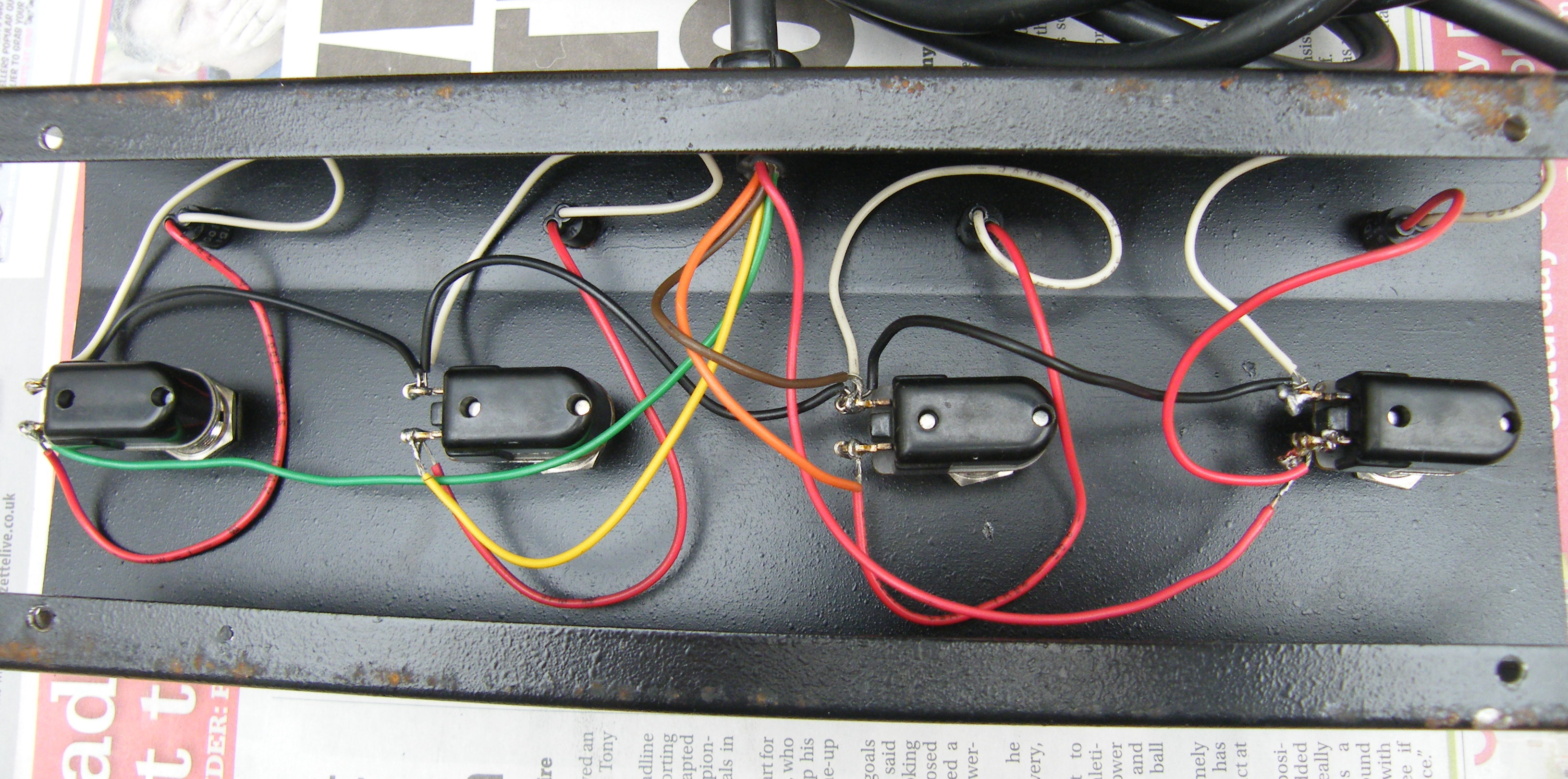
wiring colours in the right-hand photo are (left to right) green (equaliser), yellow (effects), orange (reverb), channel (red). The brown wire in the middle is common ground.
Use either footswitch with any of the 3 amps
The London and Showman both have the same 4
functions on the footswitch; the Montreux has only 3. You can use
a 3-button switch with the London and Showman but you will only be
able to select the equaliser (graphic EQ) in and out by using the
push-switch on the front panel. You can use the 4-button switch
with the Montreux but one button (equaliser) will not be used,
because that amp hasn't got a graphic EQ.
Where can I buy one?
No idea, sorry. If you find out please let me know! Voodooman
Switches used to list both types but are no longer trading.
What's Inside
The amp may be complicated, but the switching
action inside the footswitch is simple. For each function there is
only a switch with a LED wired across its terminals. On the left
below is a diagram for the Montreux. This is the interior view, so
the button labels are reversed (channel is on the left when the
switch is the right way up). The London and Showman have an
additional 'equalizer' switch (graphic EQ on/off) which is
wired up in exactly the same way using a green wire. 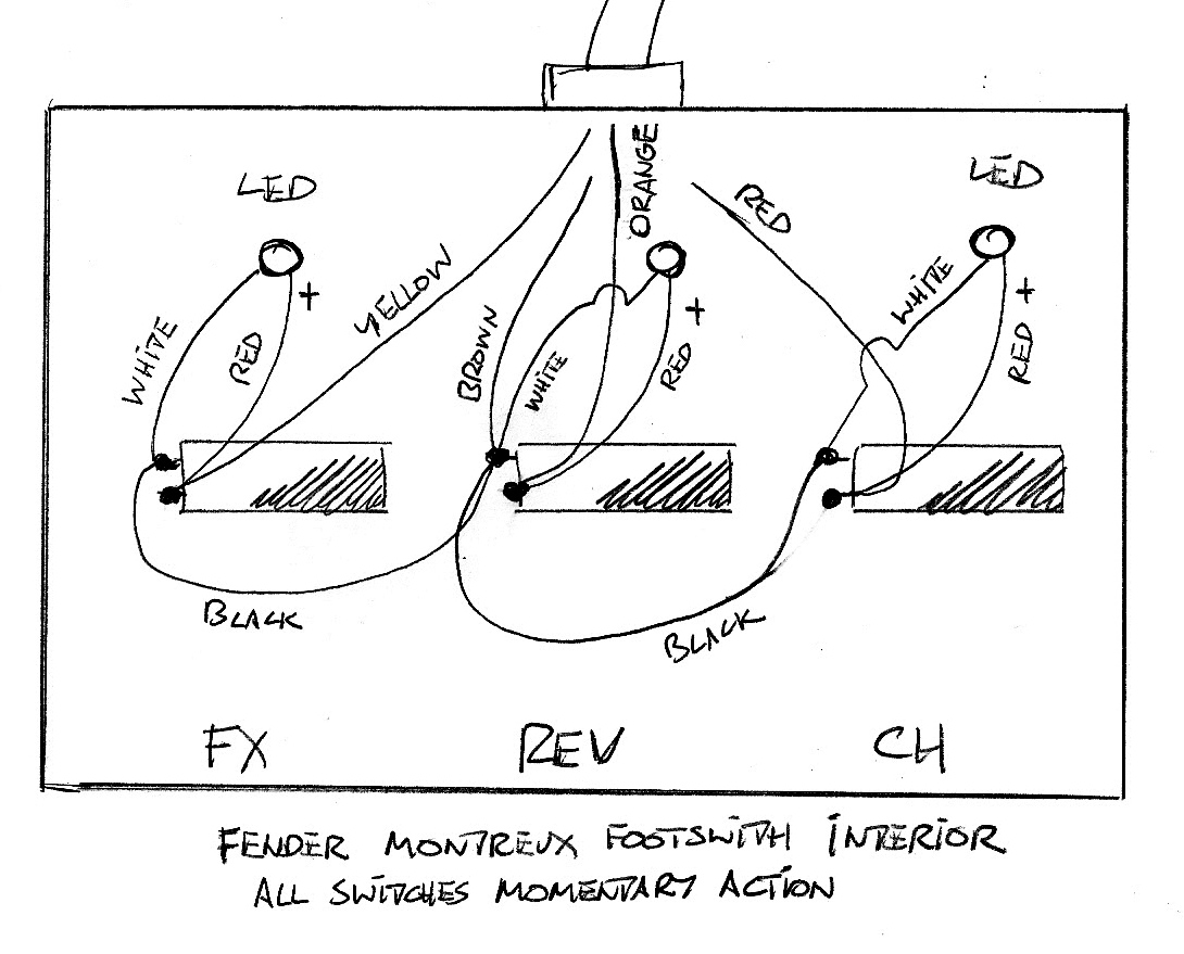
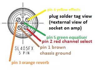
the coloured drawing above shows the wires as
they meet the solder tags inside the connector
As shown in the diagram above right, the
wiring to the 5-pin connector is as follows:
pin 1
brown
chassis ground, 0V (not connected to the footswitch box)
pin 2
red
channel select
pin
3
orange
reverb
pin
4
yellow
effects loop
pin 5
green
equaliser (4-button); on the 3-button type this is
not used
Please note that the pin numbers shown on the 'Logic and
Switching' schematic for the amp are not the same and
probably refer to some jumpers inside the amp.
The 5-pin connector is a Switchcraft SL405MX,
which includes the locking ring to secure the connector in its
socket on the amp. On Switchcraft's
drawing it's shown in the top right-hand corner. The pin
numbers there are shown for the solder tags, NOT the pins visible
when the connector is fully assembled. I lifted that drawing for
the pinout shown above.
LEDs come with one leg longer than the other. The long leg
goes to the + connections and the short leg to the common ground.
The original switches are Carling 110-PM-OFF. These are still
available, for example from Mouser on both sides of the Atlantic.
Other brands are around and they will be fine, so long as they are
heavy duty push switches, momentary action, normally off (= "push
to make" "non-latching"), 12mm mounting hole. Examples - for
mainland Europe, Thomann PF4520 and for UK, Maplin N92AP.
Some models have more than 2 terminals - they're OK but you'll
only be using 2. The box's mounting holes have the tiny 'keys' to
match the Carling and stop them rotating in the hole. These little
stubs of metal can be filed off easily if a replacement switch
doesn't have the matching groove.
The whole footswitch could be built with the connector, 3 or 4 switches, 3 or 4 LEDs, a suitable rugged box, a suitable length (original is 4.5 metres) of 4- or 5-way cable (must be 5-way for 4 buttons), and a cable gland or other strain-relief. Maybe 4 little rubber feet would help. The wiring and soldering is simple compared with the task of making the finished article tough, reliable and presentable.
For these amps, the switching action is all
done in electronic logic inside the amp. Every time the amp is
switched on, it starts in channel 1, with reverb, effects and
graphic all off. The footswitch LEDs are all off. In this state, for all
four functions, there is +1.4V on the switch and LED with respect
to chassis ground. (Note, the footswitch box isn't ground.) If you
push and release a footswitch button, it makes temporary contact
(these are not latching switches). Due to some wonderful
electronic action deep inside the amp which I certainly don't
understand, the voltage now rises to +1.9V (the forward
voltage for an LED), the LED comes on, and the function changes on
the amp (channel 2, reverb on, effects on, graphic on). Press the
switch again and the situation is reversed. Whatever state the amp
was in when switched off, it will switch on next time with channel
1 selected and all options off. NB This footswitch
is a very low-voltage item and working on it while connected to
a live amp should be safe BUT it derives its power from a
mains-powered amplifier. When you remove the bottom of the
footswitch, the bare terminals exposed should be treated with
respect until voltages are checked. The main chassis of the amp
does contain lethal voltages and normal safety rules
apply.
I am not affiliated to the wonderful Fender Musical
Instrument Corporation. All trademarks and product names
acknowledged. Original designs by Fender in the 1980s. The
information on this web page is not my copyright but I would
appreciate it if you treated this write-up and all photos as (c)
Andrew Waugh 2013-15. Comments and corrections welcome. Info
offered in good faith but you act on it at your own risk. No
responsibility will be taken for damage, injury, loss of gig, or
death. By the way, if you died tonight, where would you go?